
Display device and design method for display device

a technology which is applied in the field of display device and design method, can solve the problems of preventing image separation and difficulty in making such a filter, and achieve the effect of preventing the generation of crosstalk between images

Inactive Publication Date: 2005-10-18
SONY CORP
View PDF5 Cites 22 Cited by
  • Summary
  • Abstract
  • Description
  • Claims
  • Application Information

AI Technical Summary

Benefits of technology

The present invention provides a display device and a method of designing a display device that prevents crosstalk between images without using any image separation mechanisms in the pixel. The invention is based on the principle of using an image separation filter with specific mechanisms to create a separation between the pixels. The invention also takes into account the thickness and refractive index of the materials used in the display device, as well as the angle at which light enters the display. The invention provides a display device that prevents crosstalk between images without using any image separation mechanisms in the pixel.

Problems solved by technology

Although the above-described image separation filter can be formed in a pixel on the display plane, it is difficult to make such a filter.
This caused a problem of preventing the image from being separated, that is, generating crosstalk.

Method used


Image

  • Display device and design method for display device
  • Display device and design method for display device
  • Display device and design method for display device

Examples


Embodiment Construction

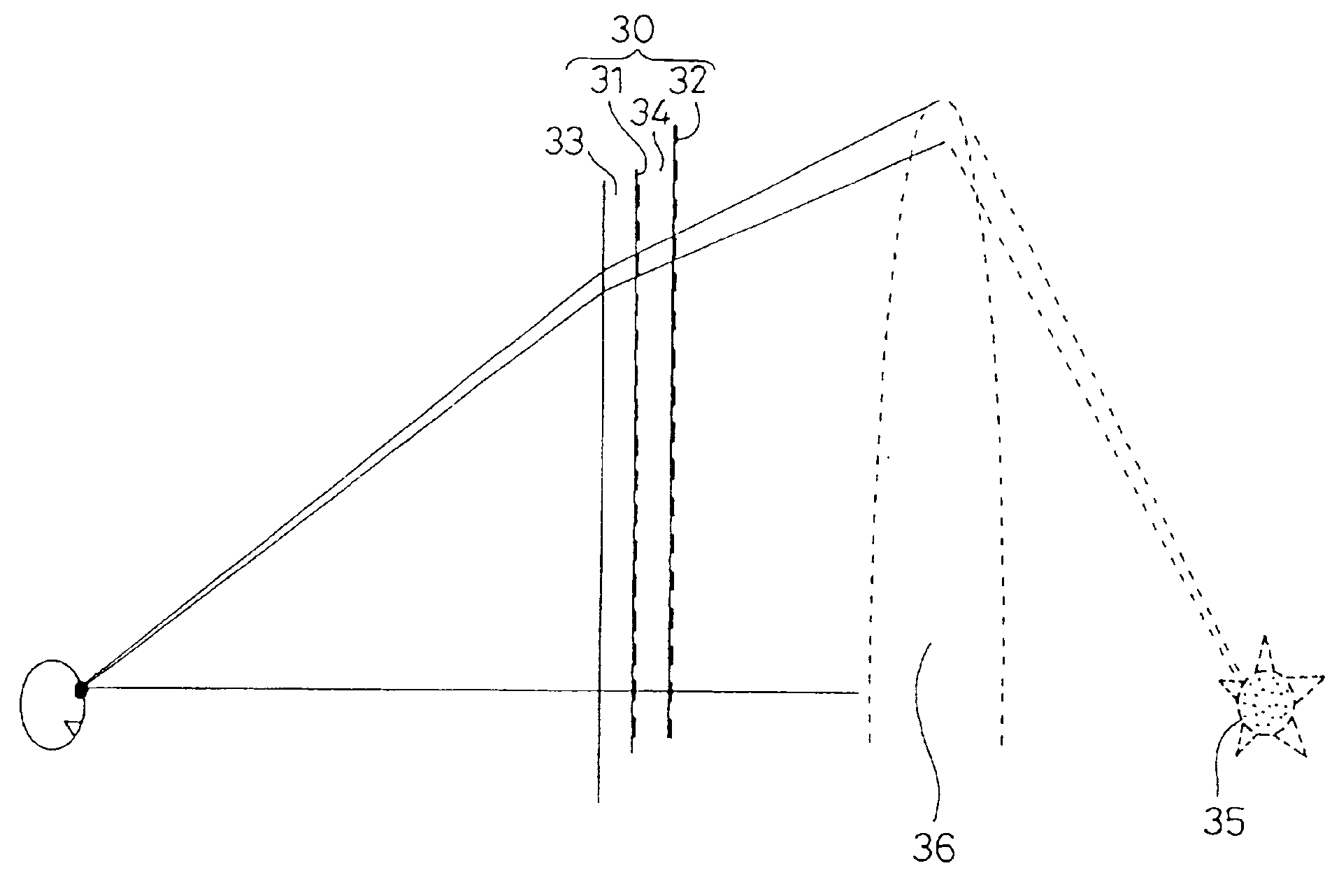
[0043]In the following, embodiments according to the invention will be explained with reference to the drawings. First, an explanation will be made about image separation mechanisms used in the invention with reference to FIG. 17 to FIG. 19. Thereafter, an explanation will be made in detail about a light converging system, a first example as one of the embodiments according to the invention, with reference to FIG. 1 to FIG. 9. After a basic explanation is finished here, an example about a light diffusing system as a second embodiment according to the invention will be explained with reference to FIG. 10 to FIG. 12. Furthermore, in FIG. 13 to FIG. 16, an example about a parallel light system as a third embodiment according to the invention will be explained.

[0044]For a display plane used in the invention, a transparent type display device is used which is represented by a slide film or a liquid crystal display element. Moreover, for the image separation mechanism, there are a method ...


PUM


Abstract

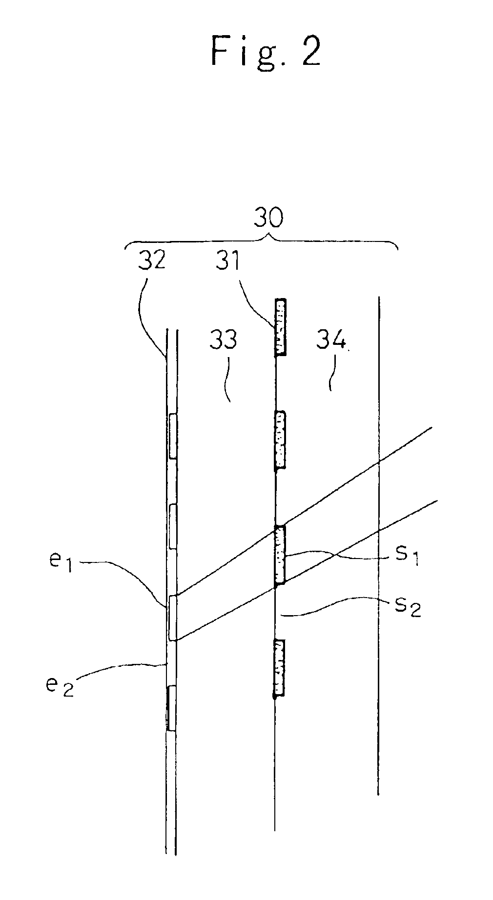
A display device having a liquid crystal display element (30) transmitting light projected from a light source to an watching point side, and including pixels (31) forming a first image region and a second image region, and an image separation filter (32) disposed from the pixels (31) through glasses (33, 34) each with a specified thickness and forming a first image separation mechanism and a second image separation mechanism, in which a calculation for obtaining the disposing interval (P1, P3) of each of the above-described image separation mechanisms of the image separation filter (32) is carried out on the basis of angles of elevation θk+1, θk, angles αk+1, αk, thicknesses W1, W2 and refractive index n of the glasses (33, 34), a distance D from the watching point to the display device, and an interval (P2) between the image regions of the above-described pixels (31) to dispose the image separation mechanisms of the above-described filter (32) with the obtained P1, P3.

Description

TECHNICAL FIELD[0001]The present invention relates to a display device and a method of designing a display device, to an image separation filter used for a display of a stereoscopic image with a binocular disparity or parallax or for a double view display that displays multi-views from one displayed image, and to a display system using the filter.BACKGROUND OF THE INVENTION[0002]There has been developed a system of displaying two or more mixed pictures on one display plane potentially having an image separation mechanism to take out each of given original images by the image separation mechanism. Such a system includes a method of separately presenting each of two images with binocular disparity between them to each of the right and left eyes in a two-dimensional image to reproduce a three-dimensional image, or a double-view display displaying multi-views from one displayed face, or the like.[0003]In the image separation mechanism used in the above-described system, the mixed pictur...

Claims


Application Information

Patent Timeline
Patent Type & Authority Patents(United States)
IPC IPC(8): G02B27/22H04N13/00
CPCG02B27/22G02B27/2214H04N13/0409H04N13/31G02B30/27
Inventor SATO, SEIJISEKIZAWA, HIDEHIKO
Owner SONY CORP
Learn More