
Short range RF network with roaming terminals

a short-range rf network and terminal technology, applied in the field of short-range rf networks, can solve problems such as system drawbacks and no longer appropriate local content supplied to terminal devices according to their location when initiating communication

Inactive Publication Date: 2005-10-11
NOKIA CORP
View PDF22 Cites 48 Cited by
  • Summary
  • Abstract
  • Description
  • Claims
  • Application Information

AI Technical Summary

Benefits of technology

"The present invention provides a system, apparatus, and method for communicating services to a wireless terminal operating within a wireless short-range network while the wireless terminal is moving through the short-range network. The wireless terminal is not limited to any present navigation structure, and provides the ability to remotely access services. The invention includes a short-range RF network comprising a plurality of nodes connected wirelessly to each other, and to at least one resource. The at least one mobile device wirelessly communicating with at least one of the plural nodes can roam out of one node's coverage area into another node's coverage area. The network is arranged to forward the user-initiated request for data to the at least one resource, which provides the requested data to a node communicating with the at least one mobile device according to the periodically updated relative information stored at the second database of the at least one resource. The technical effects of the invention include enabling seamless communication with wireless terminals as they move through a short-range network, and providing efficient data transfer between nodes."

Problems solved by technology

However, such systems experience drawbacks when a user on a terminal device roams from the coverage area of one transceiver into the coverage area of another.
One drawback of such a system is that a terminal device's Internet address changes as it roams from one node's coverage area into another, effectively terminating any Internet sessions that may have been in progress, thereby requiring new Internet connections to be made as the terminal device roams.
Another drawback of such a system is that local content supplied to a terminal device according to its location when it initiated communication may no longer be appropriate after it roams to a different transceiver's coverage area.

Method used


Image

  • Short range RF network with roaming terminals
  • Short range RF network with roaming terminals
  • Short range RF network with roaming terminals

Examples


Embodiment Construction

[0024]In the following description of the various embodiments, reference is made to the accompanying drawings which form a part hereof, and in which is shown by way of illustration various embodiments in which the invention may be practiced. It is to be understood that other embodiments may be utilized and structural and functional modifications may be made without departing from the scope of the present invention.

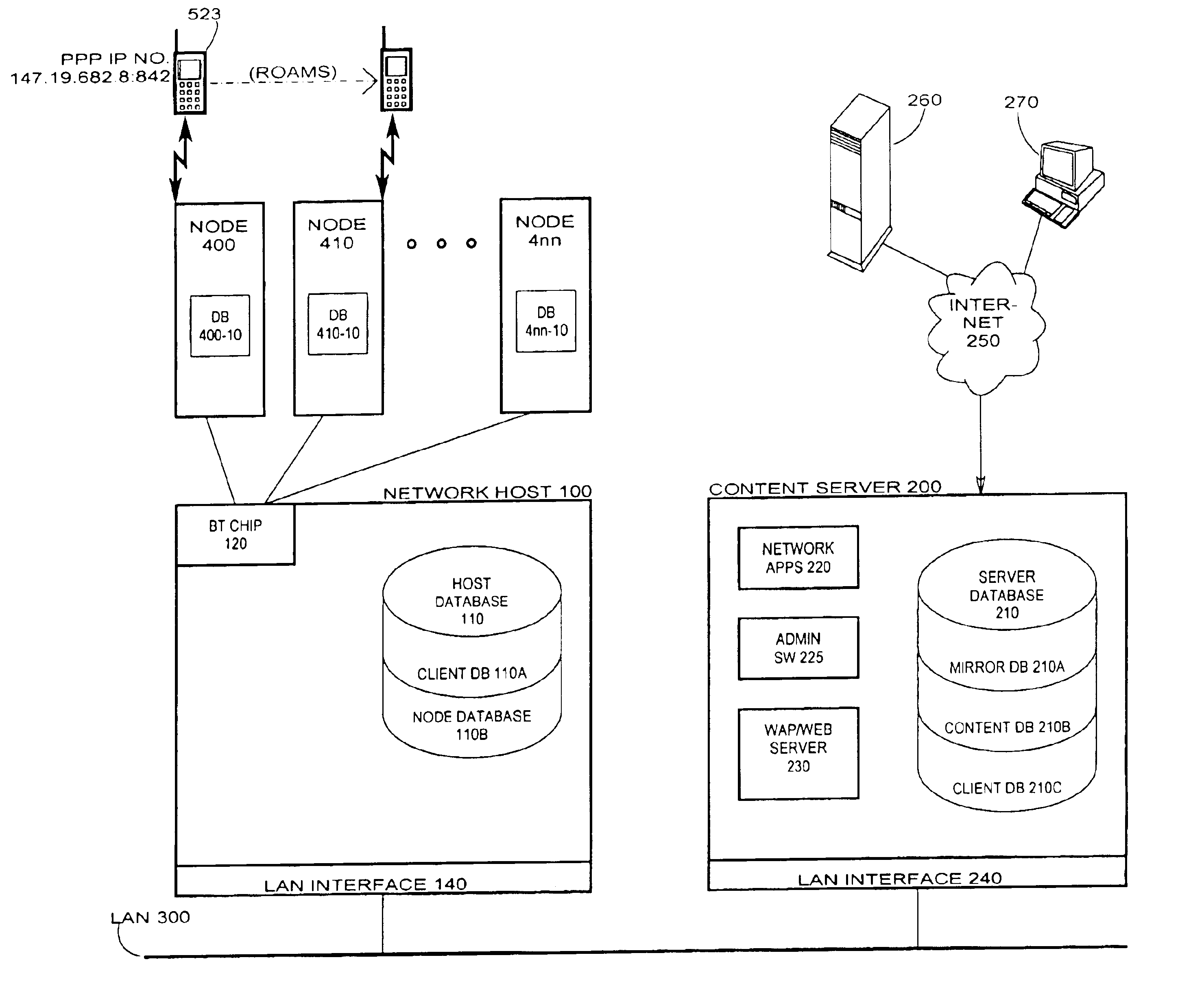
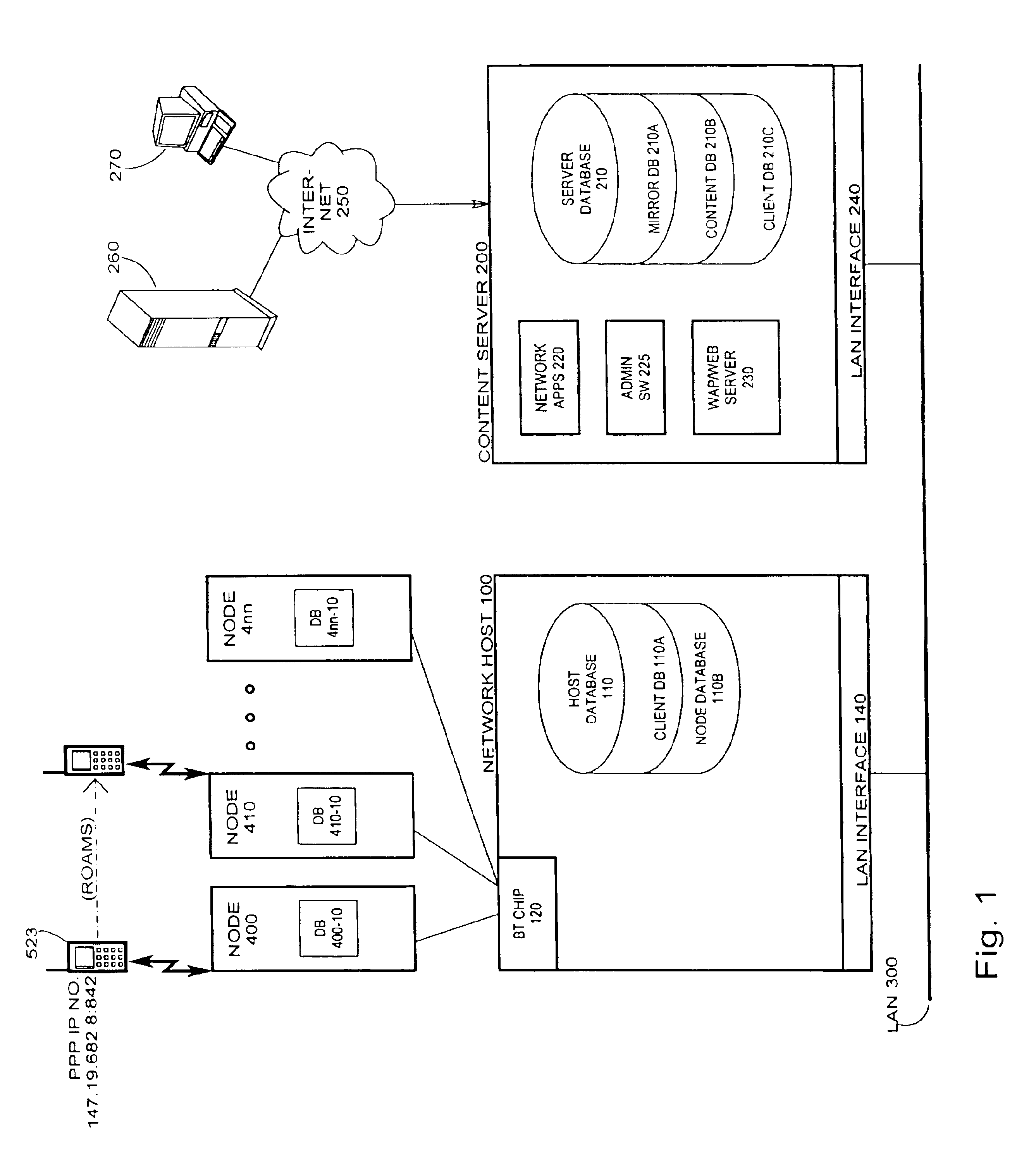
[0025]FIG. 1 is a block diagram of one embodiment of a communication system according to the present invention. Such a system would typically be deployed in a site such as a department store, shopping mall, or factory floor, i.e., an area that is relatively small, but yet is larger than could be covered by a single short-range RF transceiver which typically has a maximum range of less than 100 meters. A plurality of short-range RF transceivers 400 through 4nn are deployed as nodes and are physically positioned so as to cover the entire site, with each covering a particular...


PUM


Abstract

A short-range RF network deployed at a site larger than the coverage area of a single short-range RF transceiver includes a plurality of short-range RF transceivers deployed with overlapping coverage areas and accessible through a gateway, and accommodates terminal devices to establish communication through any transceivers with the gateway or with other of the terminal devices. The system further includes a WAP / Web server in communication with the Internet and in communication with the gateway. Terminal devices may establish Internet sessions through a node, the gateway, the WAP / Web server, and the Internet with remote Web servers or with remote users, and are assigned PPP IP numbers for such sessions. A terminal device which roams from the coverage area of one node to the coverage area of another node, and which is accordingly assigned a new PPP IP number, may continue in an Internet session by virtue of a shared database associated with the WAP / Web server and updated by the gateway. The shared database enables correlation of the terminal device's current location in the network with the PPP IP number by which Internet communications refer to it.

Description

CROSS-REFERENCE TO RELATED APPLICATIONS[0001]The present application is related to U.S. application Ser. No. 09 / 614,508, filed Jul. 11, 2000, assigned to the intended assignee of the present application.BACKGROUND OF THE INVENTION[0002]1. Field of the Invention[0003]The present invention relates to short-range RF networks and, more particularly, to client communication as a client roams through the network.[0004]2. Description of the Related Art[0005]The availability of various types of communication devices produces a need to have these devices interact with each other in a manner which is cost efficient and which can be easily implemented. Such communication can occur between two or more terminal devices (e.g. telephones, computers, printers, facsimile machines, personal digital assistants (PDAs), etc.) by wired connection such as by connecting electrical conductors to the devices, or by wireless communication using infrared signals or radio frequency (RF) signals. For many applic...

Claims


Application Information

Patent Timeline
Patent Type & Authority Patents(United States)
IPC IPC(8): H04L12/56H04L12/28H04W8/02H04W36/00H04W76/02H04W80/00H04W84/10
CPCH04W8/02H04W36/00H04W76/02H04W80/00H04W84/10H04W76/10
Inventor FORSTADIUS, ANTTIHEINONEN, TOMI
Owner NOKIA CORP
Learn More