
Expandable bit with secondary release device

Inactive Publication Date: 2005-10-11
WEATHERFORD TECH HLDG LLC
View PDF449 Cites 150 Cited by
  • Summary
  • Abstract
  • Description
  • Claims
  • Application Information

AI Technical Summary

Benefits of technology

[0015]In yet another aspect, an expandable apparatus for use in forming a wellbore is provided. The expandable apparatus includes a body and cutting members disposed on the body, the cutting members movable between

Problems solved by technology

This procedure of forming the enlarged borehole, although effective may be time consuming and expensive.
Although, this method of forming an enlarged wellbore is becoming more common the bi-center bits are unstable due to their irregular structure and tend to be more difficult to control for directional purposes than ordinary drill bits.
Additionally, the bi-center bits may not drill the expected swept diameter of the offset pads which ream the pilot hole created by the crown.
Even though the expandable bit overcomes many of the deficiencies in the conventional under-reamer and the bi-center bit, a problem still exists with the use of the expandable bit to form an enlarged wellbore.
The problem includes the possibility that the expandable bit will become stuck in the open position due to some unforeseen event, like a failure in the hydraulic fluid flow or debris that causes the blades to become jammed.
As the hydraulic fluid flows through the expandable bit, the debris builds inside the tool and eventually may affect the closing of the expandable bit.
The problem results in the expandable bit being stuck downhole because the expandable bit cannot travel through the casing in the open position.
When this problem occurs, an operator has several options, however, each option has significant drawbacks.
This option is very time consuming and costly.
Although this option is less destructive than the previous option, drilling around an obstruction requires special downhole tools that may not be available at the wellsite.
This option is problematic because the expandable bit is constructed from hardened material, resulting in a difficult milling operation that requires replacing the mill tool multiple times.

Method used


Image

  • Expandable bit with secondary release device
  • Expandable bit with secondary release device
  • Expandable bit with secondary release device

Examples


Embodiment Construction

[0029]The present invention relates to a secondary release assembly for an expandable bit. Generally, the release assembly is constructed and arranged to release blade arms of the expandable bit upon the application of a force to the expandable bit.

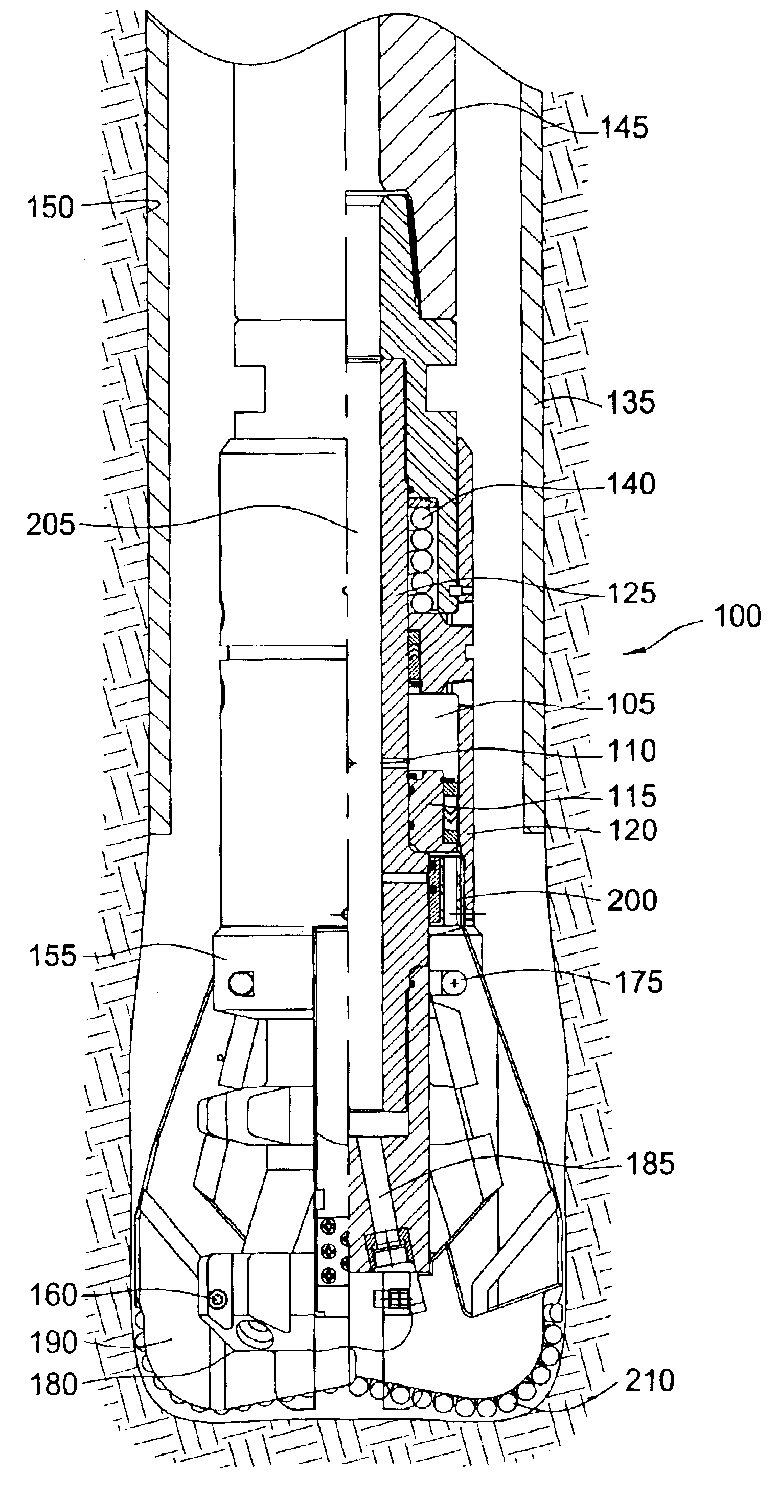
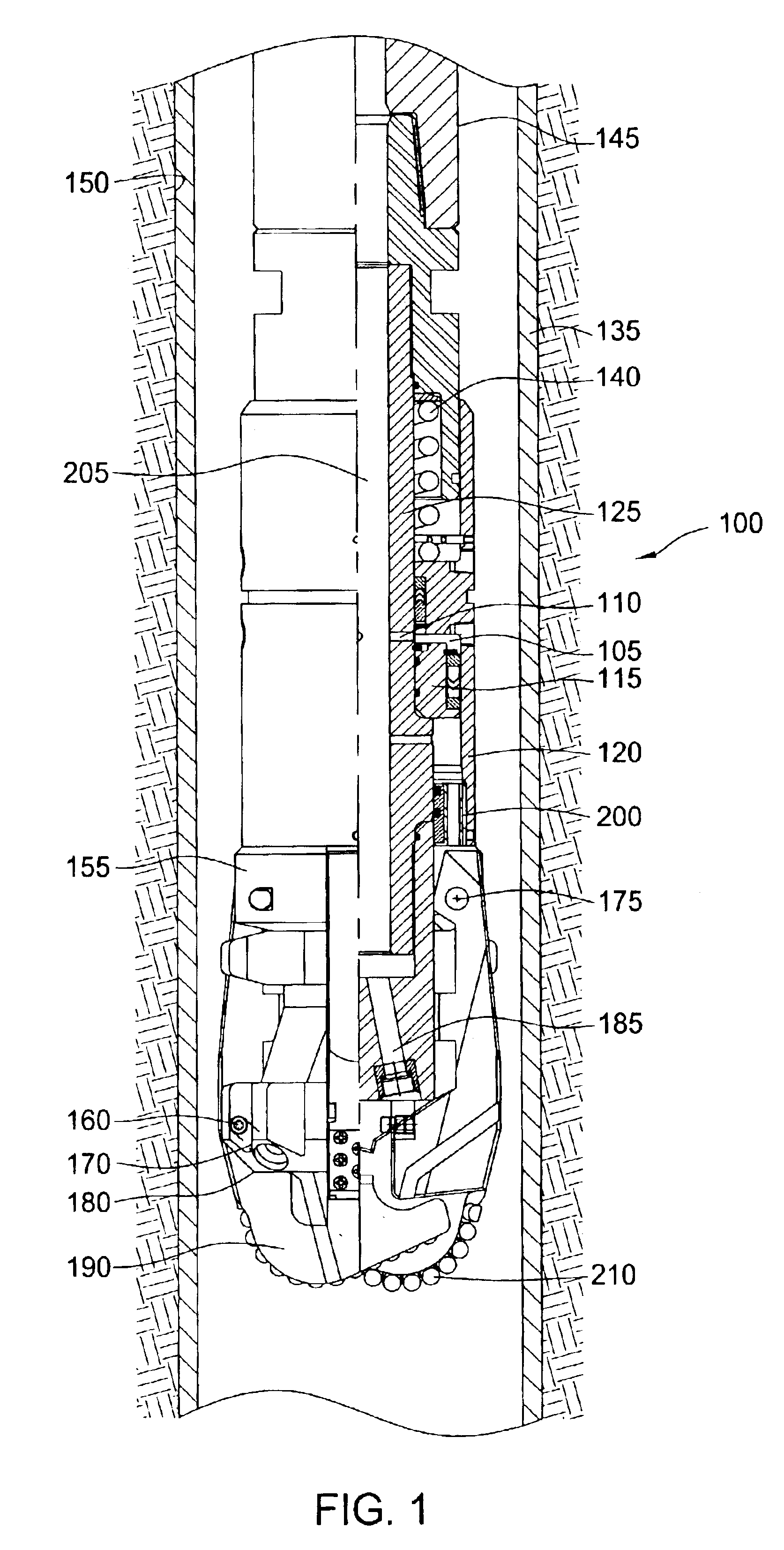
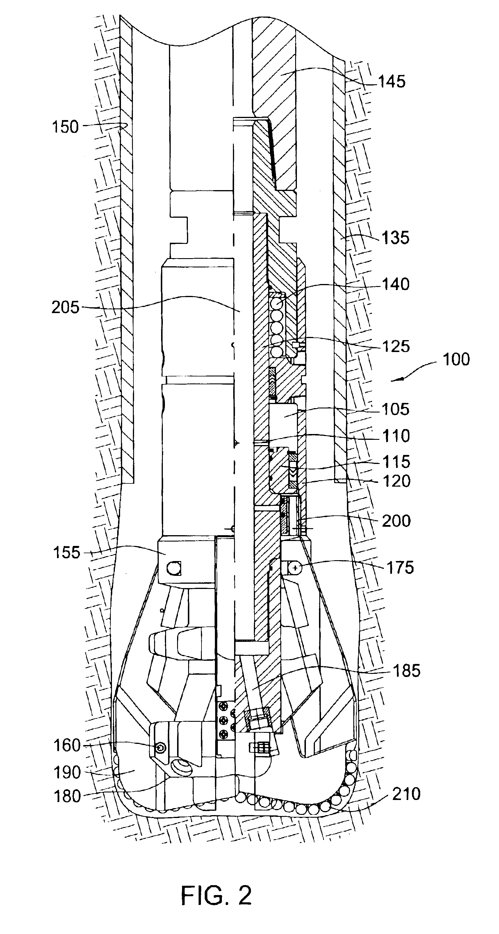
[0030]FIG. 1 is a cross-sectional view illustrating the expandable bit 100 disposed at the lower end of a drill string 145 and run-in wellbore 150. As illustrated, the wellbore 150 is lined with casing 135. Generally, the expandable bit 100 may move between an open position and a closed position. In the open position, (FIG. 2) arms 190 at the lower end of the expandable bit 100 are expanded outward while in the closed position the arms 190 are collapsed inward. The arms 190 are attached to a blade pivot housing 155 by a plurality of hinge pins 175. The hinge pins 175 allow the arms 190 to swing out from a body 125 of the bit 100. The arms 190 include a plurality of cutting elements 210 made of a hard material such as tungsten carbide or p...


PUM


Abstract

The present invention generally relates to an apparatus and method of forming a wellbore. In one aspect, an expandable bit for use in a wellbore is provided. The expandable bit includes a body and a blade assembly disposed on the body. The blade assembly is movable between a closed position whereby the expandable bit has a smaller outer diameter and an open position whereby the expandable bit has a larger outer diameter. The expandable bit further includes a release assembly for providing a secondary means to move the blade assembly from the open position to the closed position. In another aspect, a method of forming a wellbore is provided. In yet another aspect, an expandable apparatus for use in forming a wellbore is provided.

Description

BACKGROUND OF THE INVENTION[0001]1. Field of the Invention[0002]The present invention generally relates to wellbore construction. More particularly, the invention relates to an apparatus and method for deactivating a downhole tool. More particularly still, the invention relates to an expandable bit with a secondary release device.[0003]2. Description of the Related Art[0004]In the drilling of oil and gas wells, a wellbore is formed using a drill bit that is urged downwardly at a lower end of a drill string. The drill bit generally includes a body portion for securing the drill bit to the drill string and a crown portion to form the wellbore. After drilling a predetermined depth, the drill string and the drill bit are removed, and the wellbore is lined with a string of steel pipe called casing. The casing typically includes a smaller outside diameter than the drill bit that formed the wellbore. The casing provides support to the wellbore and facilitates the isolation of certain areas...

Claims


Application Information

Patent Timeline
IPC IPC(8): E21B10/00E21B10/62E21B10/26E21B10/32
CPCE21B10/322E21B10/62
Inventor GLEDHILL, ANDREW D.FULLER, MARK S.DALRYMPLE, KENNETH J.
Owner WEATHERFORD TECH HLDG LLC
Learn More