
Boot liner

a technology of boot and ankle straps, applied in the field of boot liner, can solve the problems of deformation of the upper part and insufficient sensation of the fitting on the ankle, and achieve the effect of adequate sensation of the upper part fitting on the ankl

Inactive Publication Date: 2005-10-11
YONEX CO LTD
View PDF15 Cites 55 Cited by
  • Summary
  • Abstract
  • Description
  • Claims
  • Application Information

AI Technical Summary

Benefits of technology

The present invention provides a boot liner that can provide a better fit and sensation on the ankle of the wearer. The upper part of the boot liner is designed to extend over the sole and form a foot receiving space. The upper part has a rear portion that supports the rear ankle and a front end that intersects with the front of the ankle. The upper part is fastened to the ankle using a main strap member with movable strap parts that can be pulled to tighten the upper part about the ankle. The movable strap parts have folding elements in the front ends that can be inserted into a pair of insertion elements. The upper part is designed to provide a comfortable fit and a snug fit to the ankle. The invention also includes a rear support that restrains the movable strap parts to prevent movement in relation to the rear portion and allows movement of the movable strap parts in relation to the upper part. The invention also provides an upper auxiliary strap member and a lower auxiliary strap member to enhance the fit and sensation on the ankle.

Problems solved by technology

In the above-mentioned conventional boot liner, the deformation of the upper part is limited to a condition in which the front ends merely come closer to each other when fastened to the ankle of the wearer, for which reason the sensation of fitting on the ankle is sometimes insufficient.

Method used


Image

  • Boot liner
  • Boot liner
  • Boot liner

Examples


Embodiment Construction

[0031]Selected embodiments of the present invention will now be explained with reference to the drawings. It will be apparent to those skilled in the art from this disclosure that the following descriptions of the embodiments of the present invention are provided for illustration only and not for the purpose of limiting the invention as defined by the appended claims and their equivalents.

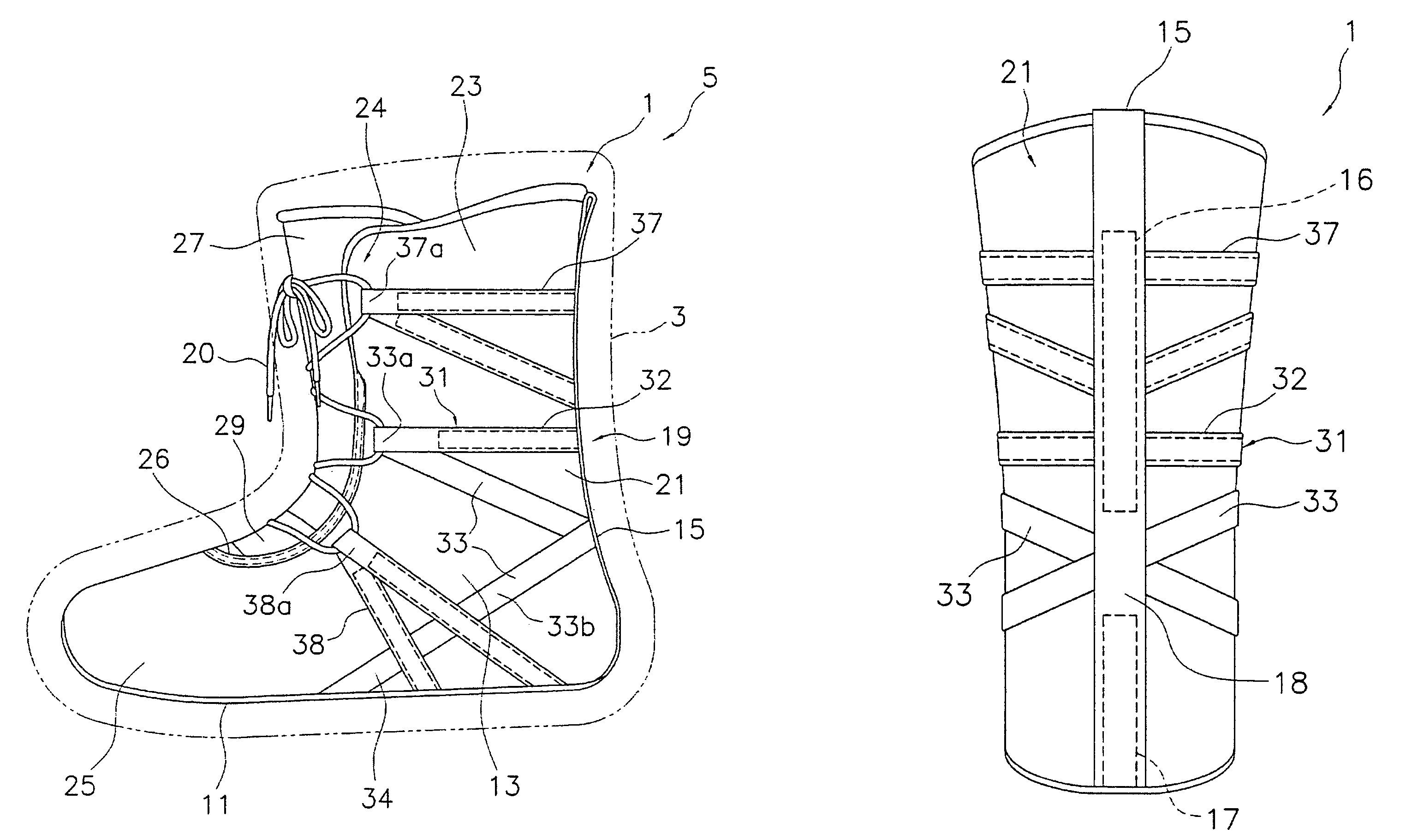
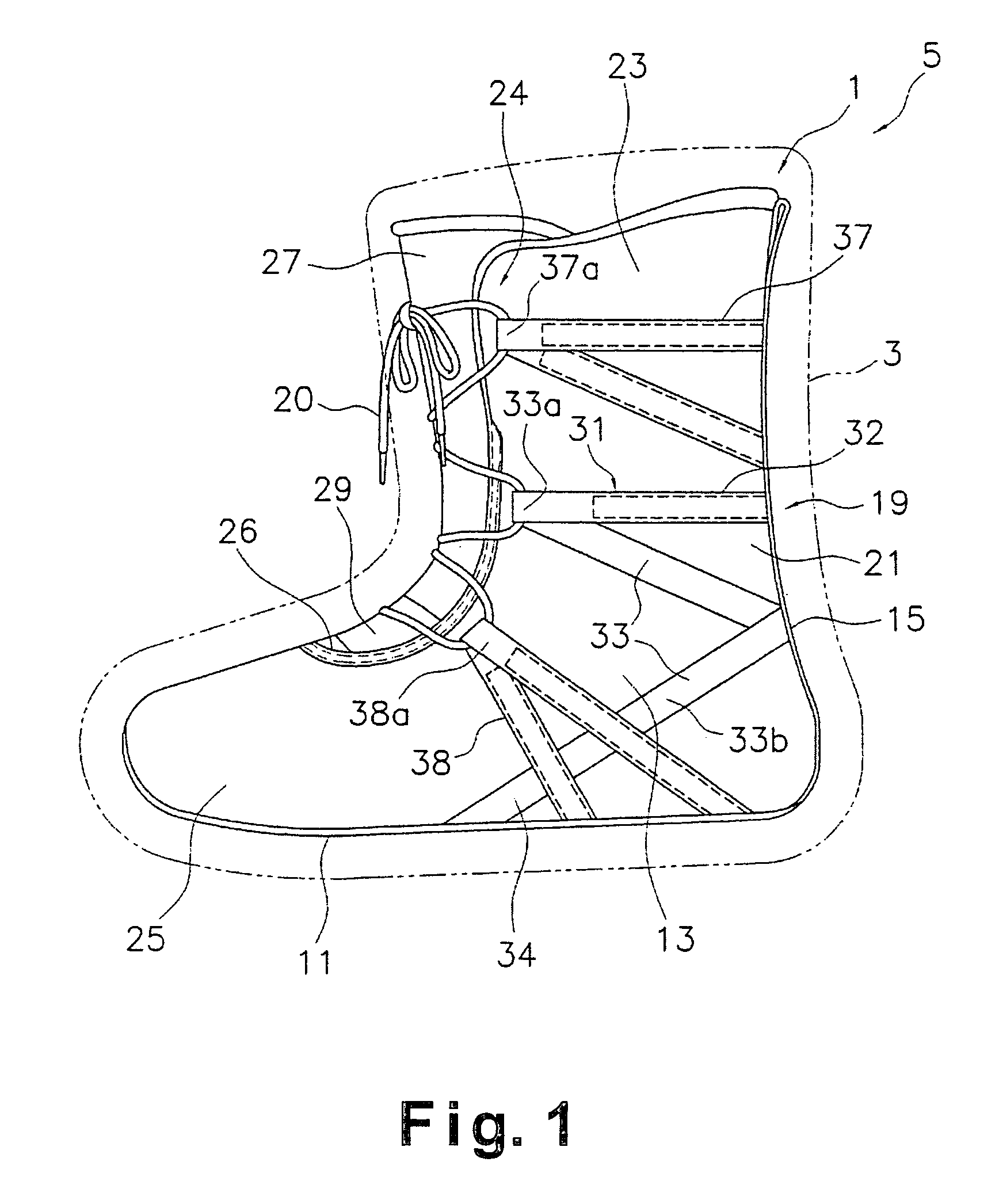
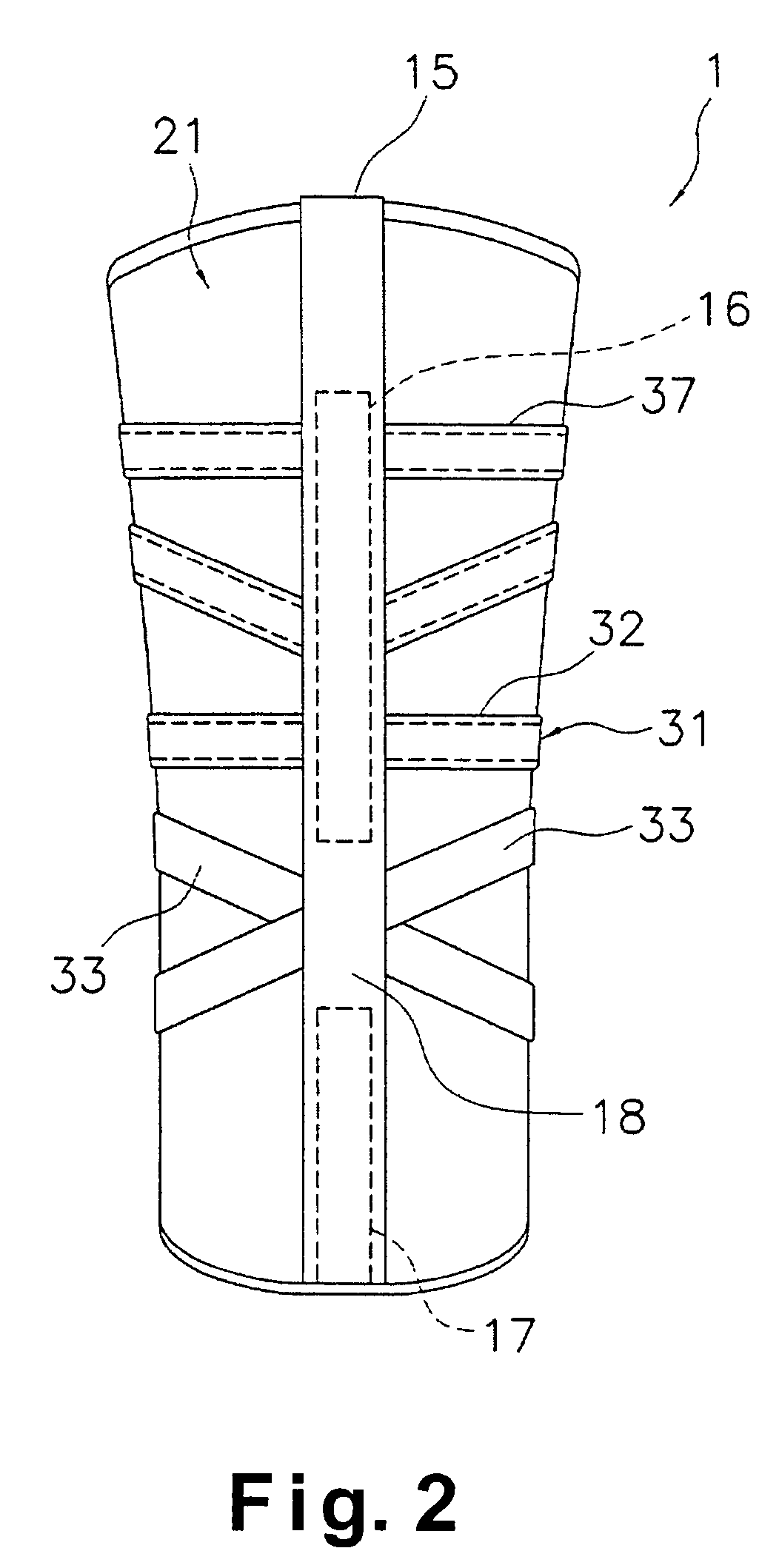
[0032]Referring to FIGS. 1–3, a boot liner 1 is illustrated in accordance with a first embodiment of the present invention. This boot liner 1 is an inner boot liner that is disposed inside an outer boot 3 of a snowboard boot 5. The boot liner 1 basically comprises a sole 11, an upper part 13, a rear support 15, and a fastening mechanism 19. The outer boot 3 is the same as a conventional outer boot and thus will not be discussed or illustrated in detail herein.

[0033]The sole 11 is the section forming the bottom section of the boot liner 1. Thus, the sole 11 has a generally foot shaped outline or per...


PUM


Abstract

A boot liner is configured to adequately obtain a desired sensation of an upper part fitting around the ankle. The boot liner has a sole, an upper part, and a fastening mechanism. The fastening mechanism has a main strap having a first fixed strap part, a pair of movable strap parts, and a second fixed strap part. The movable strap parts extend forwardly from the ends of the first fixed strap part along the side surfaces of the upper part, and are folded back such that an insertion element through which a shoelace can be inserted is formed in the vicinity of the front ends of the upper part, and the distal ends extend through the rear portion to the side surfaces on the opposite sides of the upper part. The movable strap parts intersect each other at the rear portion and can move in relation to the upper part.

Description

BACKGROUND OF THE INVENTION[0001]1. Field of the Invention[0002]The present invention generally relates to a boot liner. More specifically, the present invention relates to an inner boot liner for a snowboard boot.[0003]2. Background Information[0004]Ski boots, snowboard boots, and other such thermal footwear products generally comprise an outer boot disposed on the outside and a boot liner (inner boot) disposed on the inside of the outer boot. In most cases boot liners are configured in a shape and a material so as to provide warmth to the wearer's feet, shock absorption, good foot comfort, and the like.[0005]Boot liners generally comprise a sole forming the bottom portion of the boot and an upper part formed extending over the top of the sole so as to cover the foot and ankle of the wearer. The upper part has a rear portion for supporting the rear section of the ankle, and a pair of side parts that support the side sections of the ankle and are integrally formed with the rear port...

Claims


Application Information

Patent Timeline
Patent Type & Authority Patents(United States)
IPC IPC(8): A43C1/00A43B19/00A43B5/04A63C5/00
CPCA43B5/0405A43C1/00A43B19/00
Inventor HIRAYAMA, SHUICHI
Owner YONEX CO LTD
Learn More