
Soil manipulating tool

a technology of manipulating tools and soils, applied in the field of soil manipulating tools, can solve the problems of not being easy to do, not being easy to remove composted materials with a shovel or other conventional tool, and being difficult to remove composted materials from these containers

Inactive Publication Date: 2005-10-04
GLOBAL ENVIRONMENT MANAGEMENT FZC
View PDF18 Cites 75 Cited by
  • Summary
  • Abstract
  • Description
  • Claims
  • Application Information

AI Technical Summary

Benefits of technology

[0015]In another advantageous embodiment of the invention the tool may include a blade member which extends across the cavity at one spiral of the helical or spiral soil penetrating portion. In this embodiment of the invention the blade has the effect of loosening soil within the cavity upon rotation of the tool whilst enabling a plug of soil above the blade to be removed upon extraction of the tool from the soil. This leaves a hole with a mass of loosened soil at the bottom of the hole which is therefore able to be used for the planting of seedlings or small plants.
[0017]This embodiment of the invention may also include a liquid pump which can be attached to the hollow tube to facilitate pumping of the fluid through the tool. This embodiment is advantageous in applying a liquid fertilizer or water to the soil as the soil is manipulated by the tool.
[0020]In other embodiments the tool includes means for increasing the size of a bore created by the soil penetrating portion when the soil penetrating portion is wound through the soil.

Problems solved by technology

However, the removal of the composted material from these containers is somewhat more difficult.
It is possible that the composted material can be tipped out of the container although, depending on the nature of the container, this may not be easy to do.
Also, because of the height of this type of composting container, it is not easy to remove the composted material with a shovel or other conventional tool.

Method used


Image

  • Soil manipulating tool
  • Soil manipulating tool
  • Soil manipulating tool

Examples


Embodiment Construction

[0026]Preferred embodiments of the invention will be described, by way of example, with reference to the accompanying drawings in which;

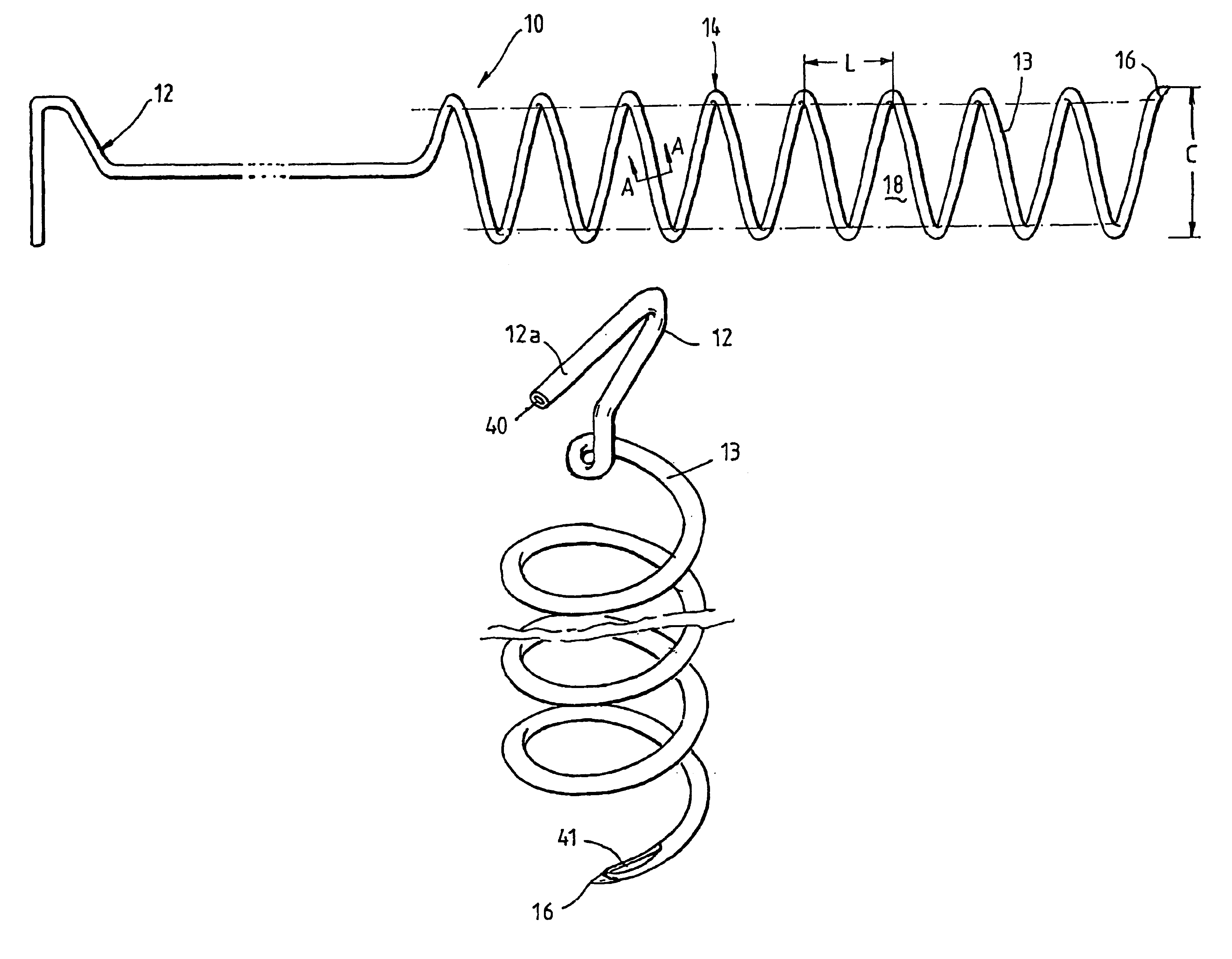
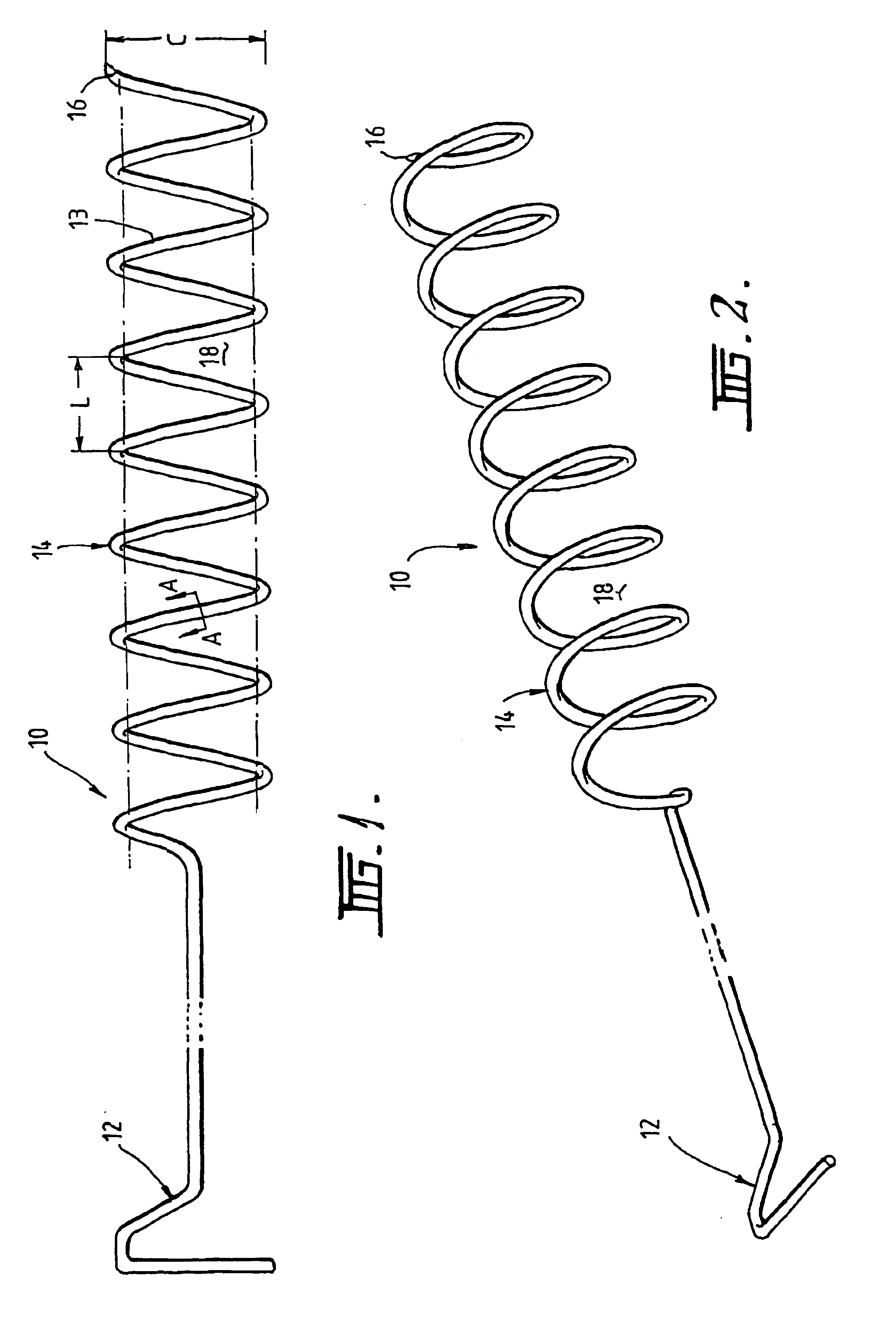
[0027]FIG. 1 is a side view of a tool embodying the invention;

[0028]FIG. 2 is a perspective view of the tool of FIG. 1;

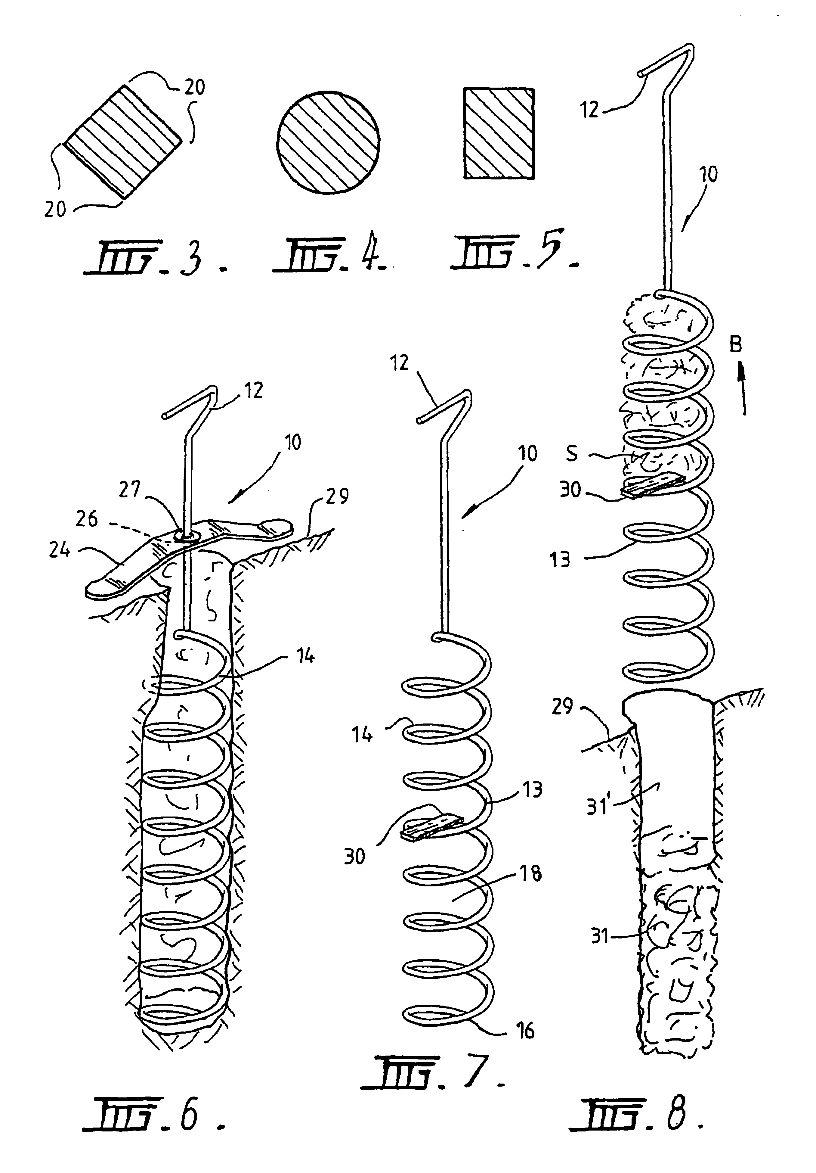
[0029]FIG. 3, FIG. 4 and FIG. 5 show various different cross-sections along the line A—A of FIG. 1;

[0030]FIG. 6 is a view of a further embodiment of the invention;

[0031]FIG. 7 is a view of a still further embodiment of the invention;

[0032]FIG. 8 is a view showing use of the embodiment of FIG. 7;

[0033]FIG. 9 is a still further embodiment of the invention;

[0034]FIG. 10 is a view of a modification to the embodiment of FIG. 9; and

[0035]FIG. 11 is a modified form of the embodiment of FIG. 9;

[0036]FIG. 12 shows a further embodiment;

[0037]FIGS. 13, 14, 15, 16, 17, and 18 show various different configurations of the tool according to still further embodiments of the invention.

[0038]With reference to FIGS. 1 and 2 a soil manipulating tool 10...


PUM


Abstract

A soil manipulating tool is disclosed which has a handle (12) and a soil penetrating portion (14). The soil penetrating portion (14) is formed from a helical or spiral rod or wire (13) which defines a cavity (18). The rod or wire (13) may be hollow so that fertilizer or other liquid material can pass through the hollow rod wire (13) into the soil in which the tool is to be used. The tool may also include an abutment member for limiting the amount of penetration of the tool into the soil to facilitate churning up of the soil and a blade may also be provided across one of the spirals of the portion (14) to provide a chopping of soil so that a hole can be formed by removal of a plug of soil but at the same time leaving loosened soil at the bottom of the hole. The tool has particular application in aerating and manipulating composted material and the removal of composted material from a compost bin as well as garden applications for the formation of holes, and the aeration of soil facilitating plant growth.

Description

FIELD OF THE INVENTION[0001]This invention relates to a soil manipulating tool. As used in this specification and the accompanying claims the term “soil” includes other generally friable substances of a similar nature including compost.[0002]The tool according to the present invention has a particular application, but not exclusive application in domestic gardening and removal of compost from a compost bin.PRIOR ART[0003]As is common, during the course of gardening it is often necessary to plant small plants or seedlings and to do so a relatively small hole needs to be dug. Conventional tools for digging such holes includes small spades and hoes.[0004]During domestic composting of material it is common to compost material in a compost container which has an open bottom so that the composted material is simply left lying on the ground. In this situation the compost is generally easy to move from one place to another with a spade because the compost container can be removed from the c...

Claims


Application Information

Patent Timeline
Patent Type & Authority Patents(United States)
IPC IPC(8): A01B1/00
CPCA01B1/00
Inventor MORRISON, MICHAEL JOSEPH
Owner GLOBAL ENVIRONMENT MANAGEMENT FZC
Learn More