
Long wavelength, pure silica core single mode fiber and method of forming the same

Active Publication Date: 2005-09-20
LUNA ENERGY
View PDF16 Cites 36 Cited by
  • Summary
  • Abstract
  • Description
  • Claims
  • Application Information

AI Technical Summary

Benefits of technology

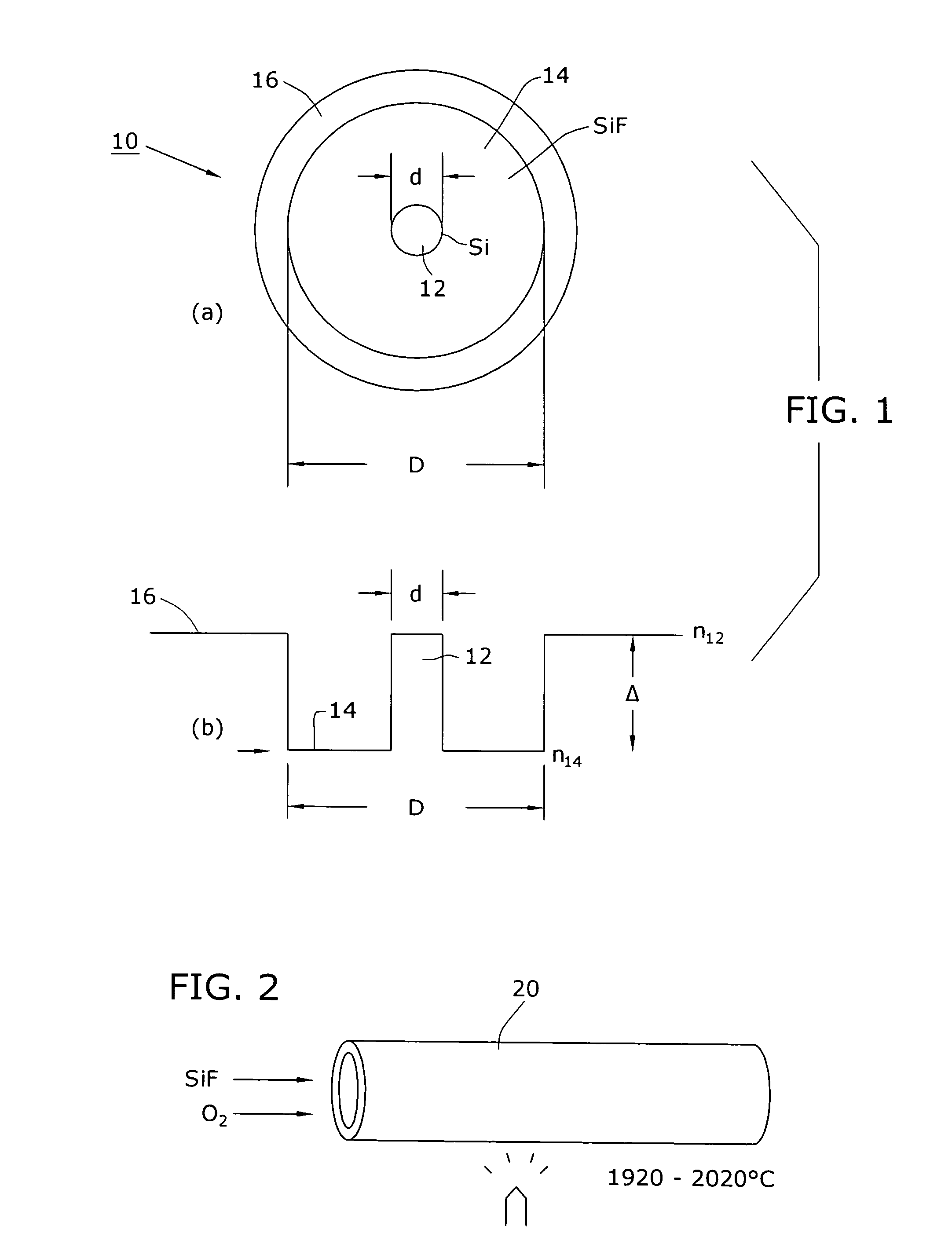
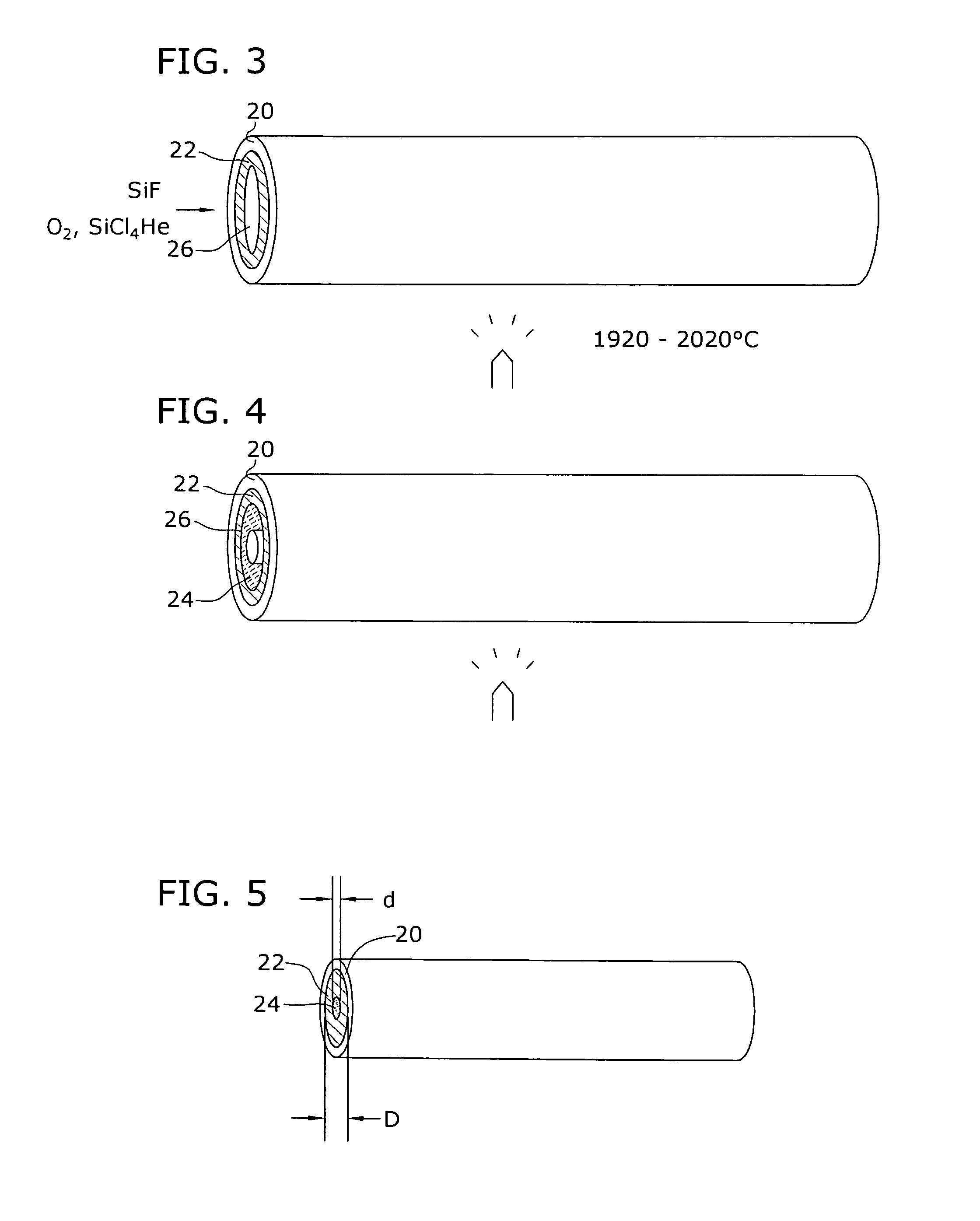
[0007]In accordance with the present invention, the core, is formed from pure silica, with a relatively thick cladding comprising fluorine-doped silica. The addition of the fluorine species serves to reduce the effective refractive index of the cladding material with respect to the pure silica core material. Using conventional MCVD processes, approximately 15–90 layers of fluorine-doped silica are deposited within a glass perform tube, with the core material thereafter deposited over the deposited layers of fluorine-doped silica.

Problems solved by technology

Therefore, for a pure silica core fiber (such as fabricated by MCVD), the depressed cladding which provides the index difference necessary for a waveguide must be large enough to contain the single mode, while not allowing the energy to leak from the fiber and drastically increase attenuation at the specified wavelength.

Method used


Image

  • Long wavelength, pure silica core single mode fiber and method of forming the same
  • Long wavelength, pure silica core single mode fiber and method of forming the same
  • Long wavelength, pure silica core single mode fiber and method of forming the same

Examples


Embodiment Construction

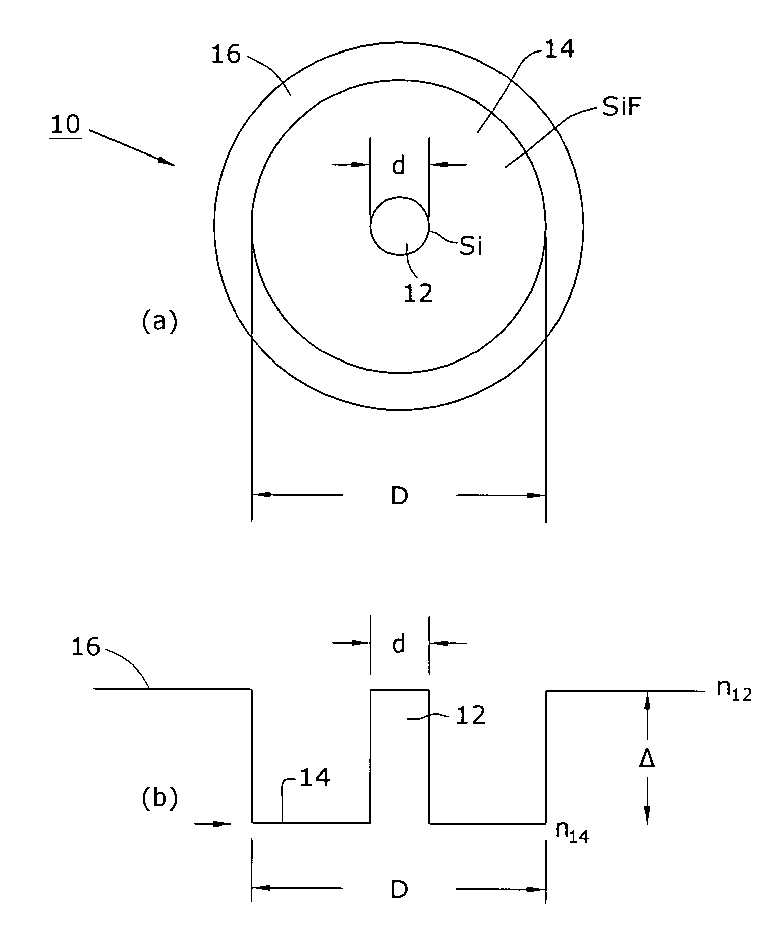
[0013]FIG. 1 contains a cross-sectional view (FIG. 1(a)) and associated refractive index profile (FIG. 1(b)) of a long wavelength, single mode fiber 10 formed in accordance with the present invention. The fiber comprises a relatively small diameter pure silica core region 12, where the diameter of core region 12 is referred to as “d” in the illustrations. A relatively thick cladding layer 14 surrounds core region 12, where the diameter of cladding layer 14 is defined as “D” in the illustrations. In accordance with the present invention, cladding layer 14 is doped with fluorine, which functions to lower the effective refractive index of the material, ensuring that most of the propagating signal will remain in the core region. A “tube” layer 16 is shown as surrounding cladding layer 14, where tube layer 16 may also comprise pure silica. FIG. 1(b) illustrates the refractive index profile for fiber 10, where the difference between the refractive index of the core (defined as n12) and th...


PUM

PropertyMeasurementUnit
Nanoscale particle sizeaaaaaaaaaa
Wavelengthaaaaaaaaaa

Abstract

An optical fiber suitable to support single mode optical transmission at longer wavelengths (e.g., 1550 nm) is formed to comprise a pure silica core region and a “down doped” cladding layer. The core region is defined as having a diameter d and the cladding layer is defined has having an outer diameter D. In accordance with the present invention, single mode propagation will be supported when D / d>8.5, and is preferably in the range of 9–10.

Description

TECHNICAL FIELD[0001]The present invention relates to a single mode fiber for long wavelength (e.g., λ=1550 nm) applications and, more particularly, to a single mode fiber comprising a pure silica core and a relatively thick cladding such that the ratio of the diameter of the cladding (defined as “D”) to the diameter of the core (defined is “d”) is greater than 8.5.BACKGROUND OF THE INVENTION[0002]In single mode optical fibers, a significant fraction of the total guided energy is not confined to the core, and the “tail” of the power distribution extends a considerable distance into the cladding material. Since the substrate (or sleeve) tube material outer cladding is typically less pure (and therefore much more lossy) than the cladding material, it is necessary to ensure that no significant fraction of the total power propagates in the substrate- or tube-derived material.[0003]In one type of prior art single mode fiber, referred to as a “depressed cladding” fiber, the effective refr...

Claims


Application Information

Patent Timeline
IPC IPC(8): G02B6/00G02B6/02C03B37/018
CPCC03B37/01807C03C13/04G02B6/02C03B2201/02C03B2201/12C03B2201/14C03B2201/28C03B2203/24
Inventor HOMA, DANIEL SCOTT
Owner LUNA ENERGY
Learn More