
Run and retrieval wear bushing and tool

a technology of wear bushings and tools, applied in the field of improved wear bushings, can solve the problem that the wear bushing cannot be rotated relative to the casing hanger, and achieve the effect of improving the wear bushing

Inactive Publication Date: 2005-09-20
VETCO GRAY
View PDF6 Cites 19 Cited by
  • Summary
  • Abstract
  • Description
  • Claims
  • Application Information

AI Technical Summary

Benefits of technology

[0009]A second embodiment utilizes only running-in ridges and not retrieval teeth, thus it is only a running-in tool. The wear bushing is secured to the running-in tool by rotating the running-in tool and wear bushing relative to each other as necessary to align the running-in ridge with the running-in keys, and axially moving the first tool and wear bushing relative to each other. The running-in tool is such that the first tool lands the wear bushing on

Problems solved by technology

With the anti-rotation pins in the slots, the wear bushing cannot be rotated relative to the casing hanger.

Method used


Image

  • Run and retrieval wear bushing and tool
  • Run and retrieval wear bushing and tool
  • Run and retrieval wear bushing and tool

Examples


Embodiment Construction

[0017]The present invention will now be described more fully hereinafter with reference to the accompanying drawings which illustrate embodiments of the invention. This invention may, however, be embodied in many different forms and should not be construed as limited to the illustrated embodiments set forth herein. Rather, these embodiments are provided so that this disclosure will be thorough and complete, and will fully convey the scope of the invention to those skilled in the art. Like numbers refer to like elements throughout, and the prime notation, if used, indicates similar elements in alternative embodiments.

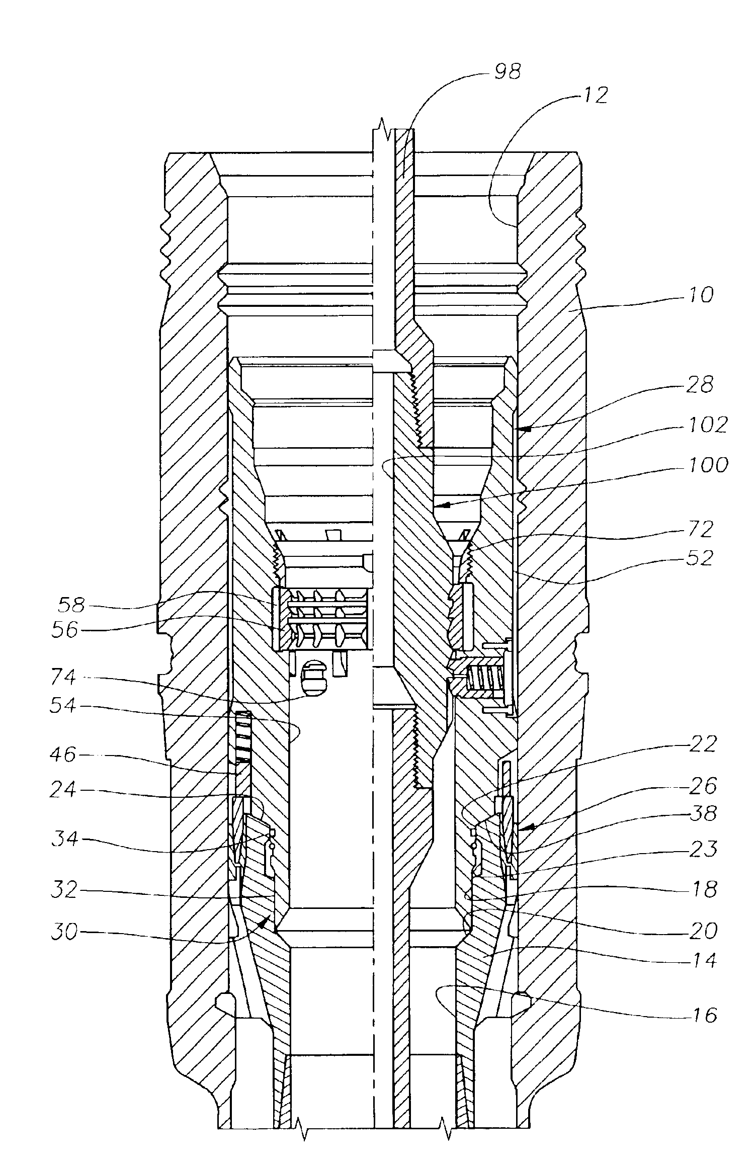
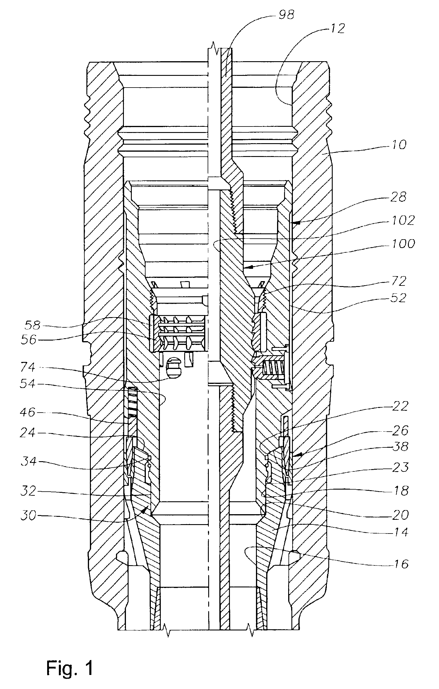
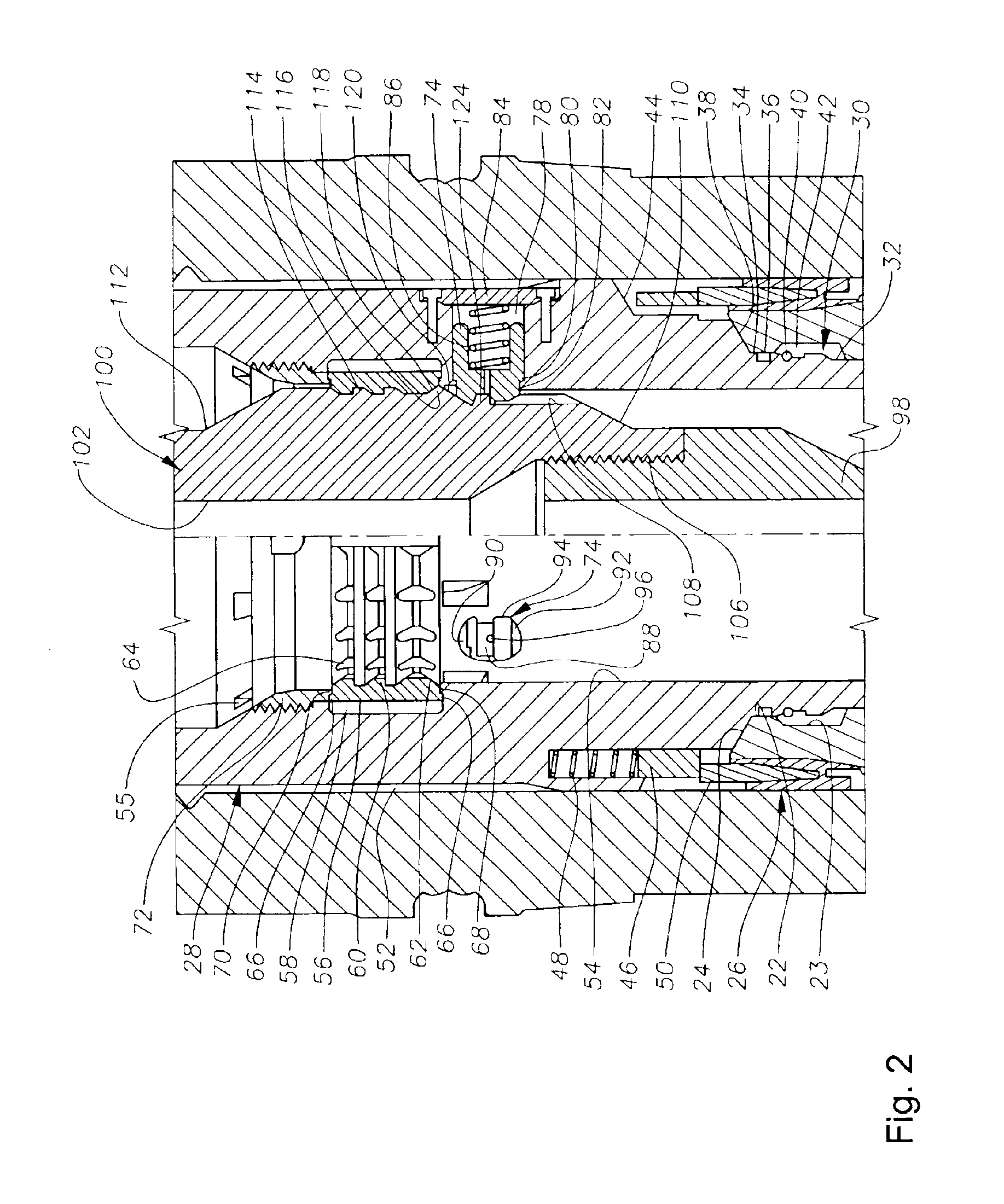
[0018]Referring to FIG. 1, a subsea wellhead has a tubular outer wellhead housing 10 with an inner bore 12. Inner bore 12 concentrically accepts a casing hanger 14 that lands in housing 10. Casing hanger 14 has a bore extending through it, with a lower section 16 separated from a middle section 18 by a conical shoulder 20. The middle section 18 has a larger diameter than...


PUM


Abstract

A wear bushing has a lower portion that is landed on a casing hanger in a wellhead housing. The wear bushing is mounted to the running tool, which is joined to a drill string. With running-in keys locked on the tool, the wear bushing is lowered down the well into the wellhead housing. The wear bushing is landed on the casing hanger and anti-rotation pins are pressed upward as they contact a seal assembly. The wear bushing is rotated until the anti-rotation pins align and fall into slots. With the anti-rotation pins in the slots, the running tool is released from the wear bushing by opposite rotation, and the running tool may then be run deeper into the well. The wear bushing is extracted using a retrieval tool. The retrieval tool is axially positioned relative to the wear bushing such that tool retrieval teeth engage a wear bushing retrieval ring so that the wear bushing can be extracted from the casing hanger.

Description

CROSS REFERENCE TO RELATED APPLICATIONS[0001]This is a continuation-in-part of U.S. patent application Ser. No. 09 / 717,870 titled “Bit Run and Retrieval Wear Bushing Tool,” filed on Nov. 21, 2000 now U.S. Pat. No. 6,749,018.BACKGROUND OF THE INVENTION[0002]1. Field of the Invention[0003]The present invention relates in general to an improved wear bushing, and in particular to an improved bit run and retrieval wear bushing and tool.[0004]2. Brief Description of Related Art[0005]A wear bushing is used in drilling applications to protect the inner profiles of the various components in the wellhead. In the prior art, wear bushings typically have been run or lowered down to the wellhead on a separate trip. One type of bit run wear bushing is held to a tool via shear pins. This bit run wear bushing has an internal ledge with a reduced inner diameter for retrieval. However, the tools used to run and retrieve the wear bushings occasionally release the wear bushings prematurely, and do not h...

Claims


Application Information

Patent Timeline
IPC IPC(8): E21B17/10E21B17/00E21B17/12
CPCE21B17/1007E21B17/12
Inventor FORD, DAVID L.MAIR, WILLIAM
Owner VETCO GRAY
Learn More