
System and method for collimating and redirecting beams in a fiber optic system

a fiber optic system and beam technology, applied in the field of optical communication, can solve the problems of little, if any, prior serious misalignment of collimated beams, and a topology that is not well suited to current injection molding technology

Inactive Publication Date: 2005-09-06
INTEL CORP
View PDF14 Cites 58 Cited by
  • Summary
  • Abstract
  • Description
  • Claims
  • Application Information

AI Technical Summary

Problems solved by technology

Most of these designs have a planar topology that is not well suited for current injection molding technology.
There is little, if any, prior art that describes a design for a TFF-based optical WDM transceiver that uses injection molding of transparent plastic to construct an integrated optical assembly.
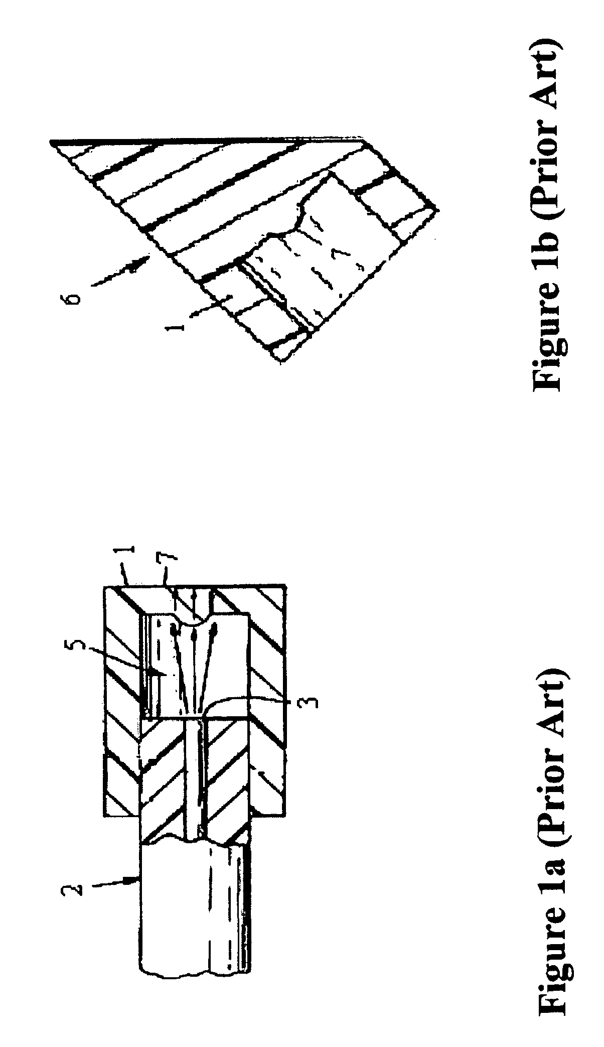
A serious disadvantage of this design and the designs of FIGS. 1a and 1b is the absence of a ferrule to guide the fiber along the axis of a collimating lens.
A small shift in fiber position results in a serious misalignment of the collimated beams.
If standard injection molding techniques were used to manufacture the design, addition of the ferrule that is necessary to refine the design would be extremely difficult because shaping the lens and ferrule on the same “slide” would generate an undercut condition.
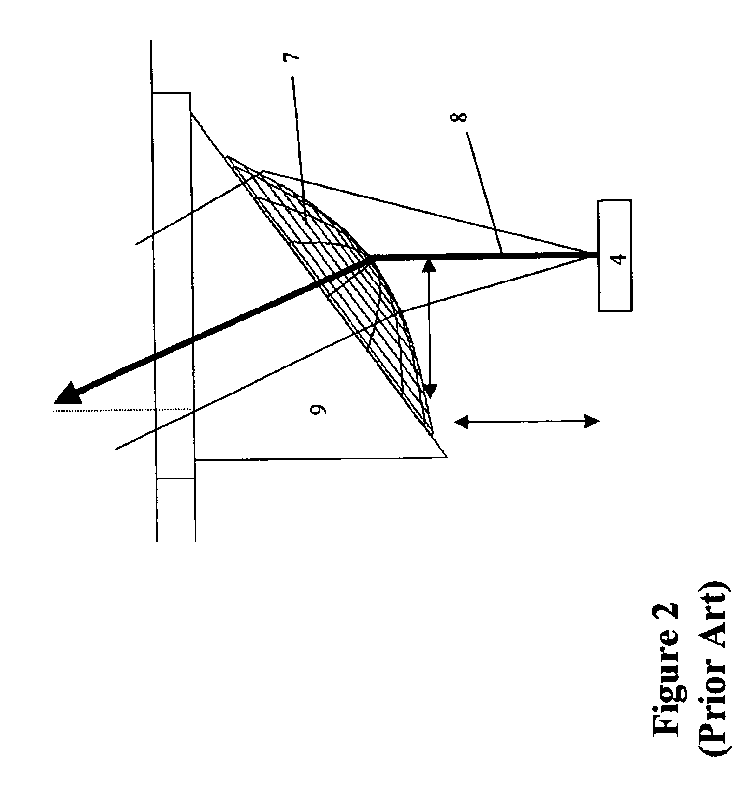
An additional problem is depicted in FIG. 2, which shows that a collimating element of related design consists of a lens surface positioned on a tilted base of refractive material.

Method used


Image

  • System and method for collimating and redirecting beams in a fiber optic system
  • System and method for collimating and redirecting beams in a fiber optic system
  • System and method for collimating and redirecting beams in a fiber optic system

Examples


Embodiment Construction

[0023]Reference will now be made in detail to the preferred embodiments of the invention, examples of which are illustrated in the accompanying drawings. While the present invention will be described in conjunction with the preferred embodiments, it will be understood that they are not intended to limit the invention to these embodiments. On the contrary, the present invention is intended to cover alternatives, modifications and equivalents, which may be included within the spirit and scope of the invention as defined by the appended claims. Moreover, in the following detailed description of the present invention, numerous specific details are set forth in order to provide a thorough understanding of the present invention. However, the invention may be practiced without these specific details. In other instances, well-known methods, procedures, and components have not been described in detail as not to unnecessarily obscure aspects of the present invention.

[0024]Embodiments of the p...


PUM


Abstract

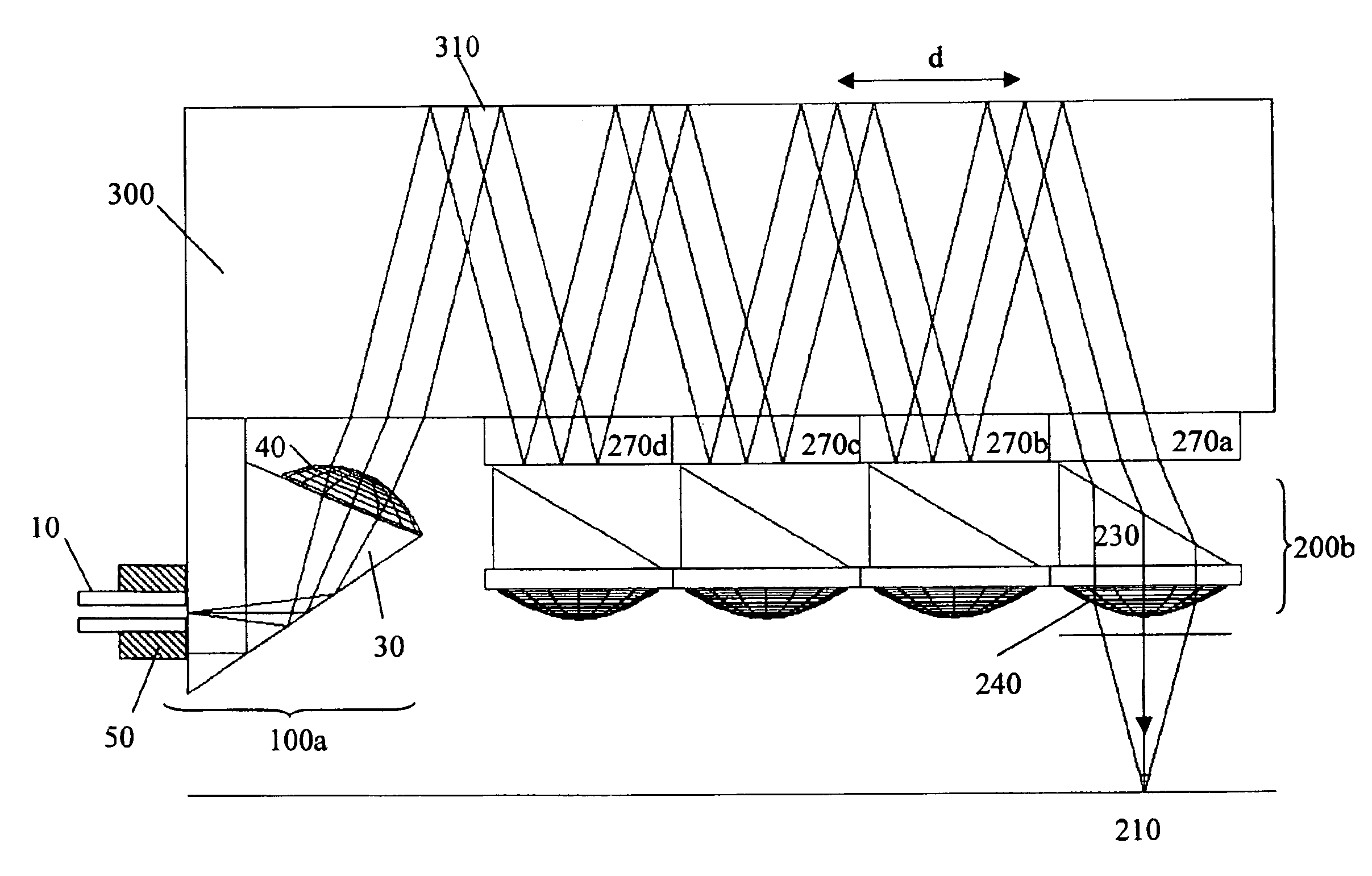
A connector to an optical fiber comprises a prism, a ferrule and an aspheric lens. The prism includes a triangular wedge element having a first surface, a second surface and a base. The ferrule guides the optical fiber so as to contact the optical fiber with the first surface of the prism. The aspheric lens is integrated on the second surface, the integrated aspheric lens being positioned so that the prism serves to redirect a light beam at an angle relative to an axis of the optical source input through total internal reflection by utilizing the base of the triangle wedge element. The aspheric lens serves to collimate the redirected light beam or focus the light beam before being redirected. This arrangement may, for example, be used within a WDM system to multiplex and de-multiplex several wavelengths of light, using a “zig-zag” optical path configuration and thin film filters to separate the wavelengths.

Description

RELATED APPLICATIONS[0001]This application is a divisional application of U.S. patent application Ser. No. 10 / 003,075, filed Oct. 31, 2001, now U.S. Pat. No. 6,751,379. This appliction claims the benefit of provisional application No. 60 / 244,941, filed Nov. 1, 2000.BACKGROUND OF THE INVENTION[0002]1. Field of the Invention[0003]The present invention relates to optical communications, and more particularly, to a system and method for collimating and redirecting beams in a fiber optic system.[0004]2. Discussion of the Related Art[0005]The integration of aspheric lenses within connectors designed to couple light beams from one optical fiber to another, and manufacturable using injection molding of optically transparent plastic, is well known. These applications generally address the need to maintain alignment between the axis of an optical fiber and a light beam output therefrom. One group of previous known designs describes the placement of a concentric plano-convex lens with the flat...

Claims


Application Information

Patent Timeline
Patent Type & Authority Patents(United States)
IPC IPC(8): G02B6/32G02B6/34G02B6/42G02B6/38
CPCG02B6/29367G02B6/32G02B6/4246G02B6/4249
Inventor CAPEWELL, DALEBEIZAI, SAM
Owner INTEL CORP
Learn More