
Motor vehicle steering device

a steering device and motor vehicle technology, applied in mechanical devices, transportation and packaging, gearing, etc., can solve problems such as difficulty in achieving proper operating feelings, and achieve the effect of compact and reliable structur

Active Publication Date: 2005-09-06
TOYODA MASCH WORKS LTD
View PDF14 Cites 26 Cited by
  • Summary
  • Abstract
  • Description
  • Claims
  • Application Information

AI Technical Summary

Benefits of technology

"The invention is a motor vehicle steering device with a variable transmission ratio mechanism that changes the way in which the driver's steering wheel movements are transmitted to the vehicle's turning wheels. The device includes a drive motor, a motor shaft, and a speed reducer. The motor shaft and the second steering shaft are in a concentric relationship, and the drive motor is fixedly installed so that it is not affected by the rotation of either the first or second steering shaft. This means that the drive motor does not rotate in conjunction with the steering wheel movements. This eliminates the need for a spiral flat cable connection, making the structure more compact and reliable. The technical effect of this invention is a more efficient and reliable steering mechanism for motor vehicles."

Problems solved by technology

However, when the transmission ratio of the motor vehicle steering device is constant, it is difficult to achieve proper operating feelings both when driving at low speeds and when driving at high speeds.
However, motor vehicle steering device 9 of the prior art has the following problems.

Method used


Image

  • Motor vehicle steering device
  • Motor vehicle steering device
  • Motor vehicle steering device

Examples


Embodiment Construction

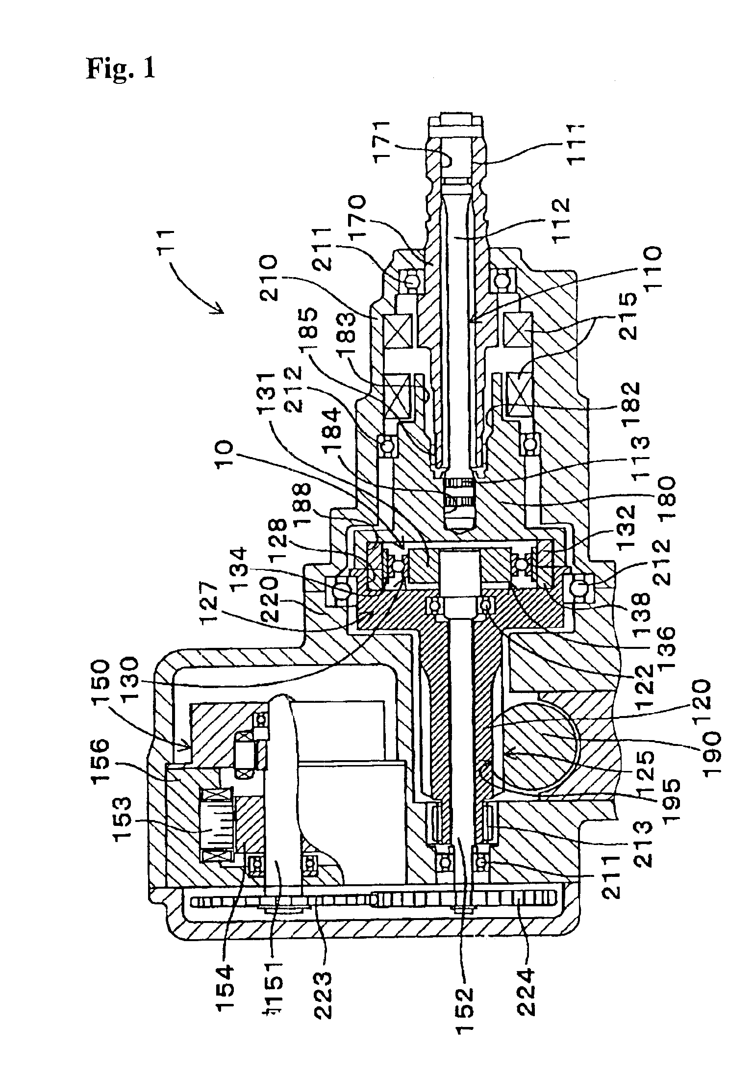
[0062]A motor vehicle steering device of an embodiment will be described below referring to FIG. 1 through FIG. 4.

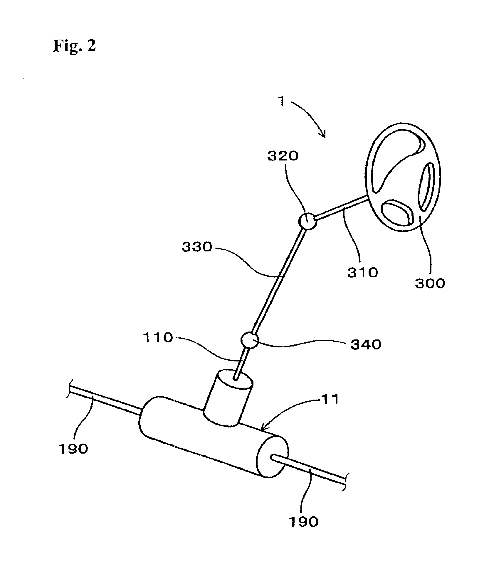
[0063]The embodiment relates to a motor vehicle steering device 1 shown in FIG. 1 comprising a variable gear ratio system 10 that varies the rotary motion transmission ratio between a first steering shaft 110 that rotates together with a steering wheel 300 (FIG. 2) and a second steering shaft 120 connected to a turning rod 190 provided for turning a turning ring (not shown).

[0064]Said variable gear ratio system 10 comprises a drive motor 150, a motor shaft 152 for transmitting the rotation of an output shaft 151 of said drive motor 150, and a Strain Wave Gearing Speed Reducer 130.

[0065]Strain Wave Gearing Speed Reducer 130 is so constituted as to change the transmission ratio between the input rotary speed from first steering shaft 110 and the output rotary speed transmitted to second steering shaft 120 depending on the rotary speed of motor shaft 152.

[0066]Motor shaft 1...


PUM


Abstract

The invention provides a compact and highly reliable motor vehicle steering device that does not require a spiral flat cable. The motor vehicle steering device includes variable gear ratio system that modifies the transmission ratio of the rotary motions between first steering shaft and second steering shaft. Variable gear ratio system comprises Strain Wave Gearing Speed Reducer that modifies the transmission ratio between first steering shaft and second steering shaft in response to the rotating speed of motor shaft. Motor shaft and second steering shaft forms a substantially concentric dual structure, drive motor is affixed, and output shaft is connected to motor shaft.

Description

INCORPORATION BY REFERENCE[0001]The present application claims priority under 35 U.S.C. §119 to Japanese Patent Application No. 2003-073953 filed on Mar. 18, 2003. The content of that application is incorporated herein by reference.FIELD OF THE INVENTION[0002]The invention relates to a motor vehicle steering device that transmits the steering angle from the steering handle to the turning ring.DESCRIPTION OF THE RELATED ART[0003]A conventional steering device transmits the steering angle of the steering wheel to the turning ring at an approximately constant transmission ratio to provide a specified turning angle. For example, in a motor vehicle steering device of a conventional rack and pinion type, the transmission ratio between the steering angle and the turning angle is determined by the mesh between the pinion gear that rotates with the steering wheel as a unit and the rack gear connected with the turning ring through a turning rod.[0004]However, when the transmission ratio of th...

Claims


Application Information

Patent Timeline
Patent Type & Authority Patents(United States)
IPC IPC(8): B62D5/00B62D5/04F16H49/00
CPCB62D5/008B62D5/0409F16H49/001
Inventor YAMAMORI, MOTOYASUWATANABE, OSAMUHONAGA, SUSUMUINAGUMA, YOSHIHARU
Owner TOYODA MASCH WORKS LTD
Learn More