Check valve

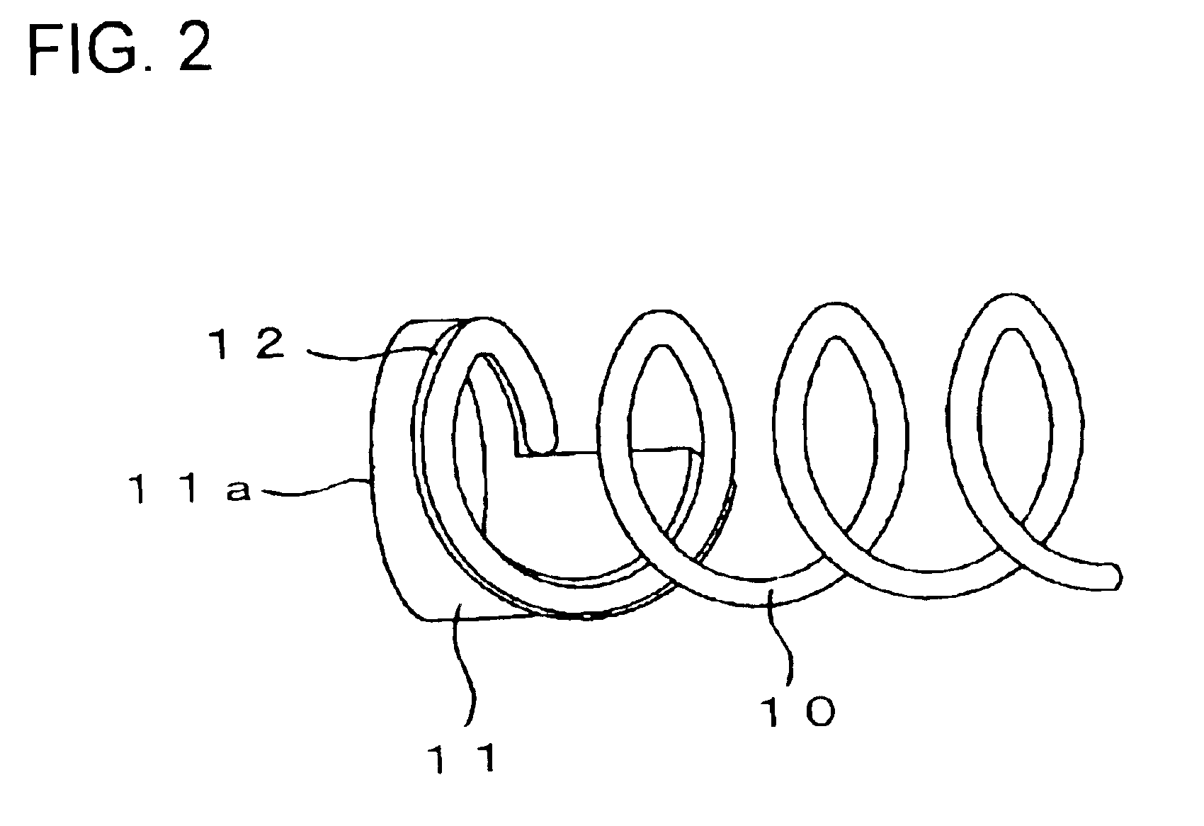
a check valve and valve body technology, applied in the field of check valves, can solve the problems of vibration, noise, and the inability to form the opposite open ends of the compression coil spring into a closed-end shape, and achieve the effect of free from vibration and noise problems

Inactive Publication Date: 2005-09-06
SURPASS IND
View PDF6 Cites 11 Cited by
  • Summary
  • Abstract
  • Description
  • Claims
  • Application Information

AI Technical Summary

Benefits of technology

[0009]Under such circumstances, the present invention was made. Consequently, it is an object of the present invention to provide a check valve free from any vibration and noise problems inherent in the conventional check valve.

Problems solved by technology

Due to the presence of such tubular element, in the art of semiconductor fabrication, it is impossible to form each of opposite open ends of the compression coil spring into a closed-end shape.
This results in leakage of the fluid in the area of the O-ring 25 when the check valve is in its closed configuration, and also results in vibrations and issuance of noise of the cylindrical valve element 23 inside the cylindrical body element 21 due to misalignment in longitudinal axis between the cylindrical valve element and the cylindrical body element 21.

Method used


Image

  • Check valve
  • Check valve
  • Check valve

Examples


Embodiment Construction

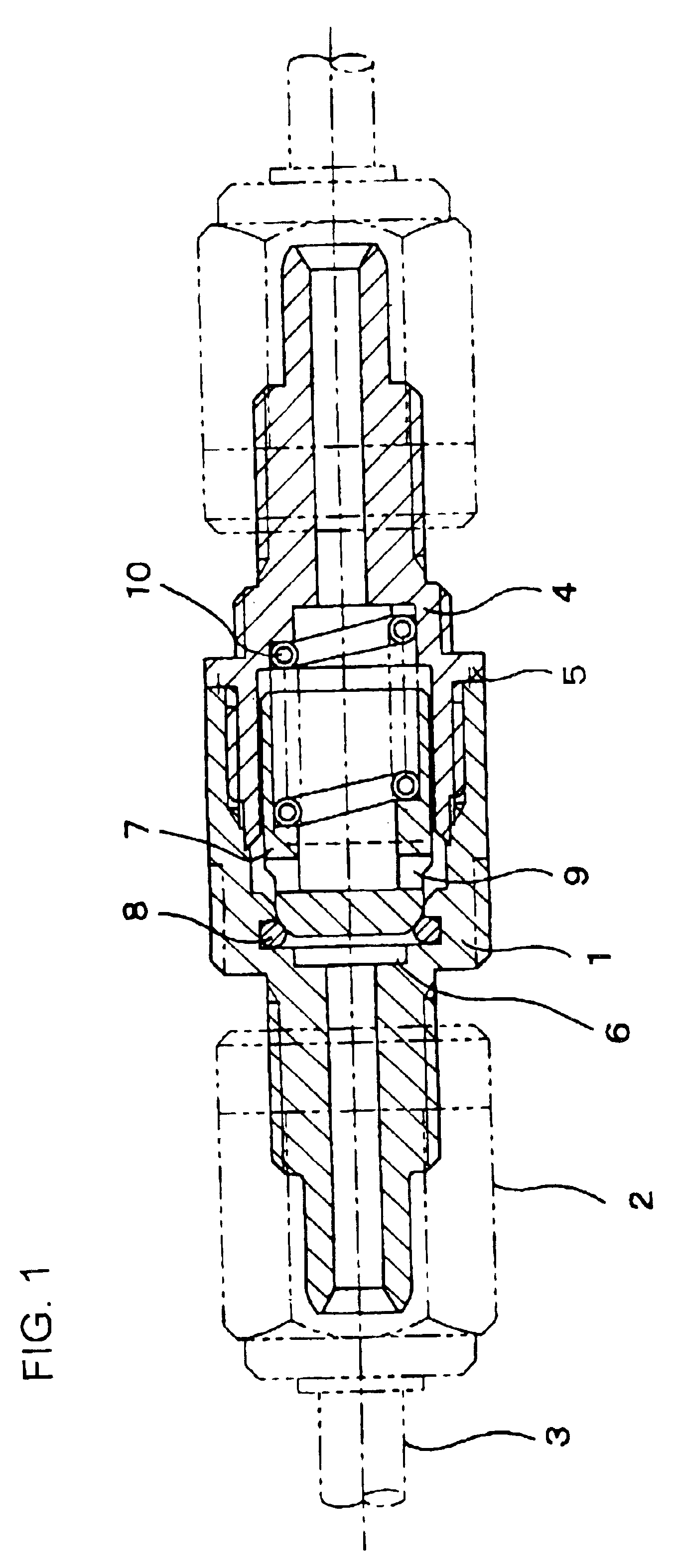
[0026]The best modes for carrying out the present invention will be described in detail using embodiments of the present invention with reference to the accompanying drawings.

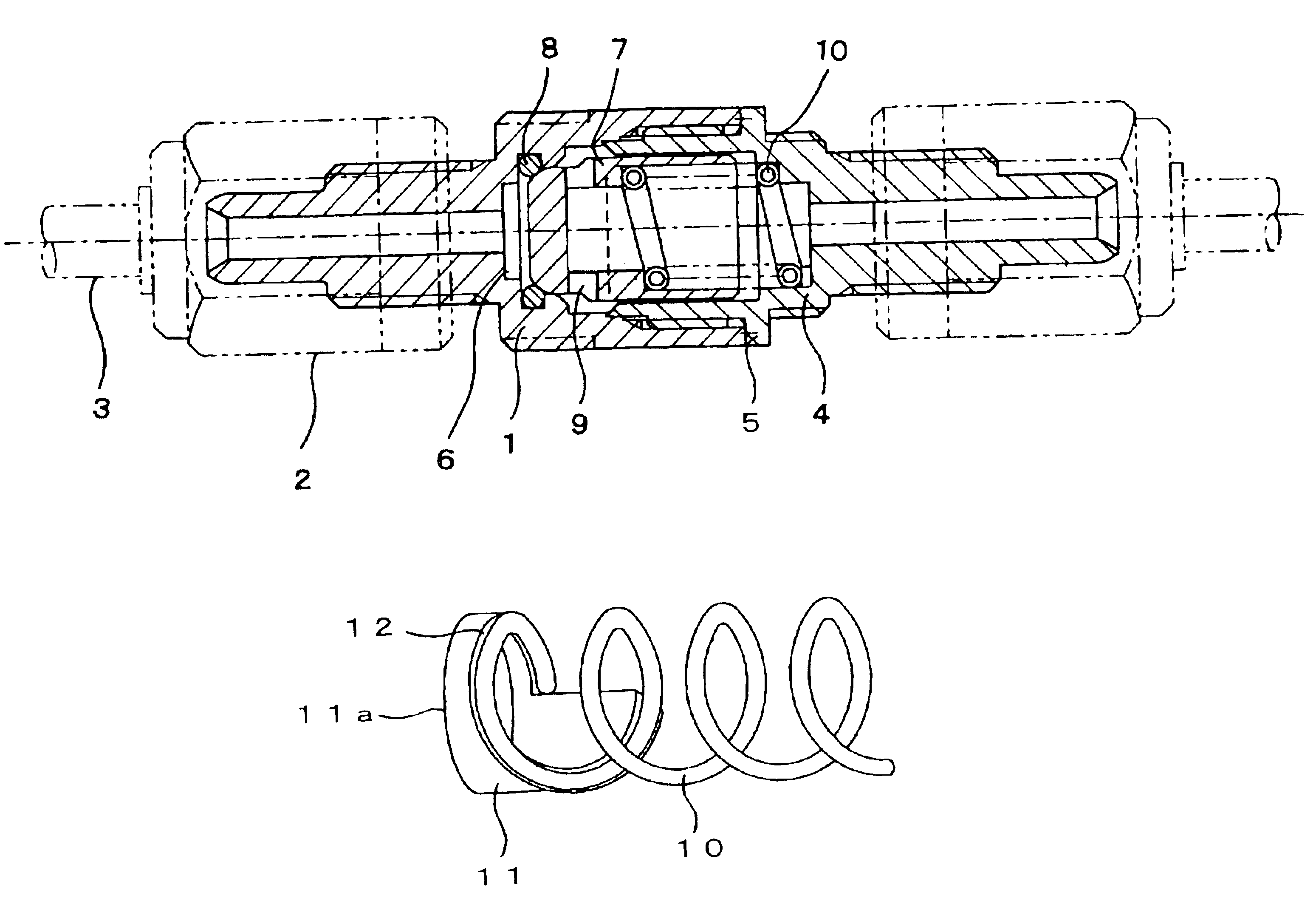
[0027]As shown in FIG. 1, an embodiment of a check valve of the present invention is provided with an upstream-side cylindrical body element 1 and a downstream-side cylindrical body element 4.

[0028]The upstream-side cylindrical body element 1 is fluid-tightly connected with an upstream-side fluid conduit 3 through an upstream-side nut member 2. On the other hand, the downstream-side cylindrical body element 4 has its upstream-side projection portion threadably engaged with a downstream-side bore portion of the upstream-side cylindrical body element 1, so that, as viewed from FIG. 1, a left-hand axial end surface of a flange portion 5 of the downstream-side cylindrical body element 4 abuts against a right-hand axial end surface of the downstream-side portion of the upstream-side cylindrical body element 1 and is...


PUM


Abstract

A check valve comprises: a pair of cylindrical body elements (1, 4) through which a fluid passes; a cylindrical valve element (7), which is disposed inside an upstream-side one (4) of the cylindrical body elements (1, 4), constantly subjected to a fluid pressure and biased toward its closed position under the influence of a resilient force exerted by a compression coil spring (10) coated with a tubular element; and, a stopper element (24) disposed in a downstream-side one (4) of the cylindrical body elements (1, 4). The check valve is characterized in that at least one of the cylindrical valve element (7) and the stopper element (24) is provided with a spiral seat portion (11) an axial spiral surface of which is brought into stable surface-contact with the compression coil spring (10) to support the compression coil spring (10) therein.

Description

BACKGROUND OF THE INVENTION[0001]1. Field of the Invention[0002]The present invention relates to a check valve, and more particularly to a check valve provided with a spring seat portion which has its spiral seat surface brought into press-contact with at least one of opposite terminal turns of a compression coil spring to support the compression coil spring.[0003]2. Description of the Related Art[0004]In general, as viewed from FIG. 3, a conventional check valve has a single cylindrical body element 21, slidably and coaxially mounted in an upstream-side portion of which body element 21 is a cylindrical valve element 23. This cylindrical valve element 23 has its inner shoulder portion brought into press-contact with one of opposite open ends of a compression coil spring 22 and is therefore constantly biased leftward to its closed position by a biasing device such as the compression coil spring 22 in a longitudinal direction of the cylindrical body element 21. Fixedly and coaxially m...

Claims


Application Information

Patent Timeline
Patent Type & Authority Patents(United States)
IPC IPC(8): F16K15/02F16K17/04
CPCF16K15/026Y10T137/7856Y10T137/7925Y10T137/7929
Inventor ABE, KOICHI
Owner SURPASS IND
Why Eureka
Try Eureka