
Method for optimizing the k-space trajectories in the location encoding of a magnetic resonance tomography apparatus

a magnetic resonance tomography and location encoding technology, applied in the field of magnetic resonance tomography, can solve the problems of insufficient fourier transformation by itself for later image reconstruction, inability to arbitrarily rotate the k-matrix in space, and inability to optimize the k-matrix sampling speed, etc., to achieve the effect of optimizing the sampling speed of the k-matrix

Inactive Publication Date: 2005-08-30
SIEMENS HEALTHCARE GMBH
View PDF14 Cites 27 Cited by
  • Summary
  • Abstract
  • Description
  • Claims
  • Application Information

AI Technical Summary

Benefits of technology

[0018]An object of the present invention is to provide an MRT apparatus and method which allow an optimally fast sampling of the k-matrix in a simpler way and for every MRT apparatus without an arbitrary shift and / or rotation of the measurement plane leading to an overload of the amplifiers.

Problems solved by technology

A Fourier transformation by itself is no longer adequate for the later image reconstruction given a sinusoidal sampling of the k-matrix.
In practical terms for a conventional gradient pulse, this means that the plane of the k-space trajectory that is used to sample the k-matrix cannot be arbitrarily rotated in space without overloading the amplifiers of the corresponding gradient coils.
Due to the conventional employment of trapezoidal or sinusoidal gradient pulses, it is difficult to avoid, given a rotation of the measurement coordinate system relative to the coordinate system defined by the gradient field directions, exceeding the amplitude and slew rate limits—adhered to by individual pulses—due to vectorial combination.
It is thus a problem in the field of MRT to be able to sample the k-matrix optimally fast but such that the gradient current function can be subjected to an arbitrary rotation without exceeding the amplitude and / or slew rate limits of the individual coils.

Method used


Image

  • Method for optimizing the k-space trajectories in the location encoding of a magnetic resonance tomography apparatus
  • Method for optimizing the k-space trajectories in the location encoding of a magnetic resonance tomography apparatus
  • Method for optimizing the k-space trajectories in the location encoding of a magnetic resonance tomography apparatus

Examples


Embodiment Construction

[0045]FIG. 5 is a schematic illustration of a magnetic resonance tomography apparatus for generating gradient pulses according to the present invention. The structure of the magnetic resonance tomography apparatus corresponds to the structure of a conventional tomography apparatus, with the differences described below. A basic field magnet 1 generates a temporally constant, strong magnetic field for the polarization or alignment of the nuclear spins in the examination region of a subject such as, for example, a part of a human body to be examined that is disposed on a patient support 5. The high homogeneity of the basic magnetic field required for the magnetic resonance measurement is defined in a spherical measurement volume M into which the parts of the human body to be examined are introduced. For satisfying the homogeneity requirements and, in particular, for eliminating time-invariable influences, shim plates of ferromagnetic material are attached at suitable locations. Time-va...


PUM


Abstract

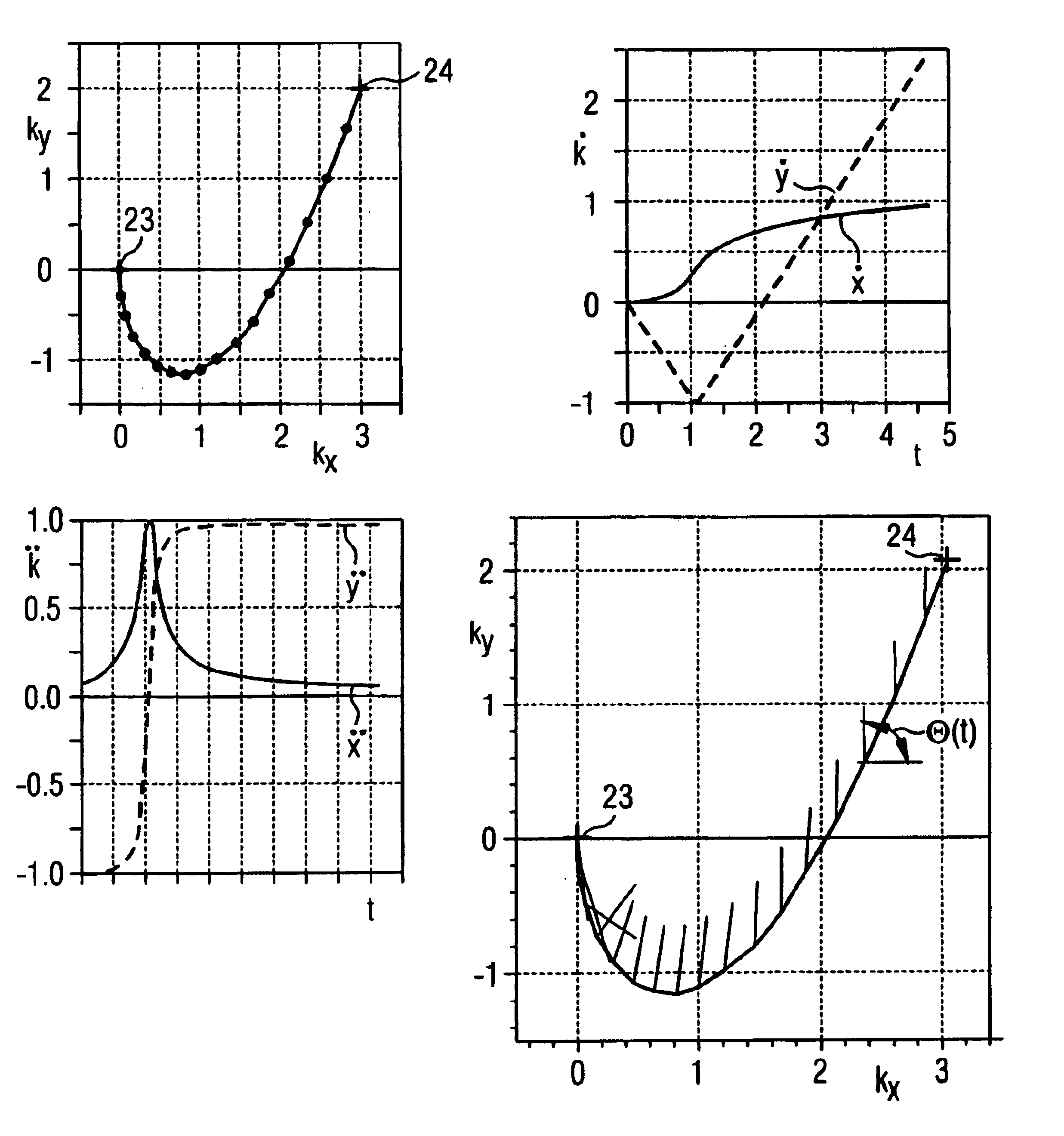
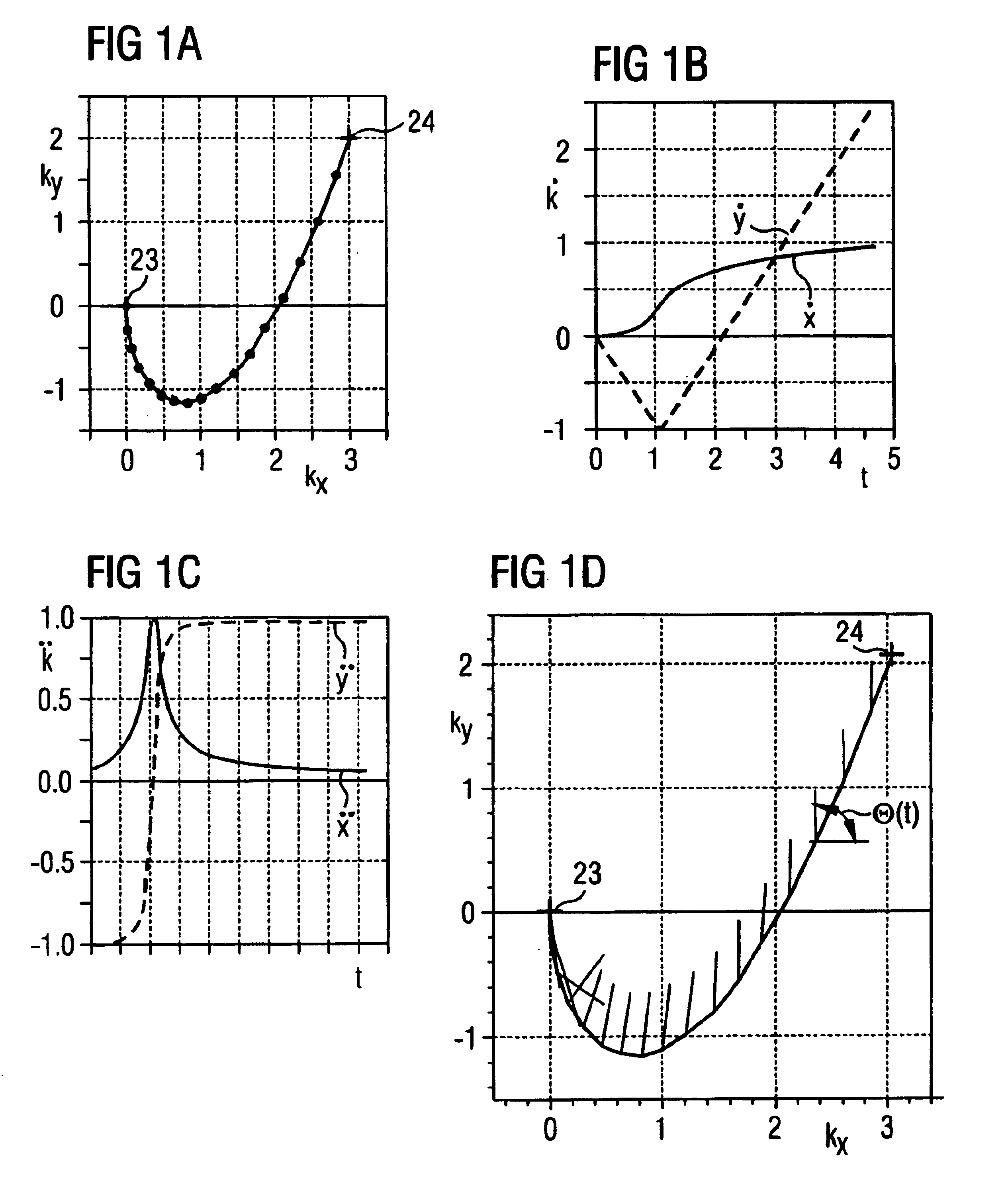
In a method and apparatus for calculating the sampling path of the k-matrix under given boundary conditions for the examination of a subject by means of a magnetic resonance tomography apparatus having a gradient amplifier with appertaining gradient coils, an input-display terminal, a sequence controller and a system computer as well as an analog-to-digital converter, boundary conditions are entered into the sequence controller or into the system computer via the input-display terminal, the sampling path of the k-matrix is calculated taking the boundary conditions into consideration by the sequence controller or the system computer, and the gradient current curves are determined by the sequence controller or the system computer that lead to a sampling along the previously calculated sampling path when applied to the corresponding gradient coils with utilization of the ADC.

Description

BACKGROUND OF THE INVENTION[0001]1. Field of the Invention[0002]The present invention is directed in general to magnetic resonance tomography (MRT) as employed in medicine for examining patients. The present invention is particularly directed to a method for the optimization of k-space trajectories in the location encoding of a magnetic resonance tomography apparatus. An optimally fast sampling of k-matrix achieved as a result thereof leads to the utmost effectiveness of the sequence employed.[0003]2. Description of the Prior Art[0004]MRT is based on the physical phenomenon of nuclear magnetic resonance and has been successfully employed in medicine and biophysics for more than 15 years. In this examination modality, the subject is subjected to a strong, constant magnetic field. As a result thereof, the nuclear spins in the subject align, these having been previously irregularly oriented. Radiofrequency energy can then excite these “ordered” spins to a specific oscillation. This osc...

Claims


Application Information

Patent Timeline
IPC IPC(8): G01R33/54A61B5/055G01R33/48
CPCG01R33/54G01R33/543
Inventor HEID, OLIVER
Owner SIEMENS HEALTHCARE GMBH
Learn More