
Vehicle-mounted electronic apparatus

Inactive Publication Date: 2005-08-30
ALPINE ELECTRONICS INC
View PDF26 Cites 13 Cited by
  • Summary
  • Abstract
  • Description
  • Claims
  • Application Information

AI Technical Summary

Benefits of technology

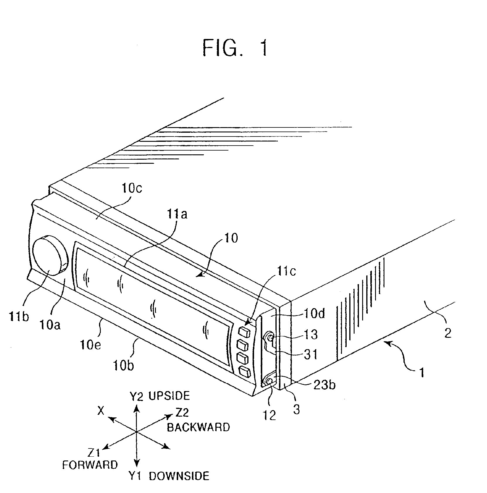
[0010]An object of the present invention for solving the above problems is to provide a vehicle-mounted electronic apparatus arranged such that when a face is located on the front portion a case, manipulation members can sufficiently project from the manipulation surface of the face, whereas when the face is accommodated in the case, the manipulation members can retract within the face.
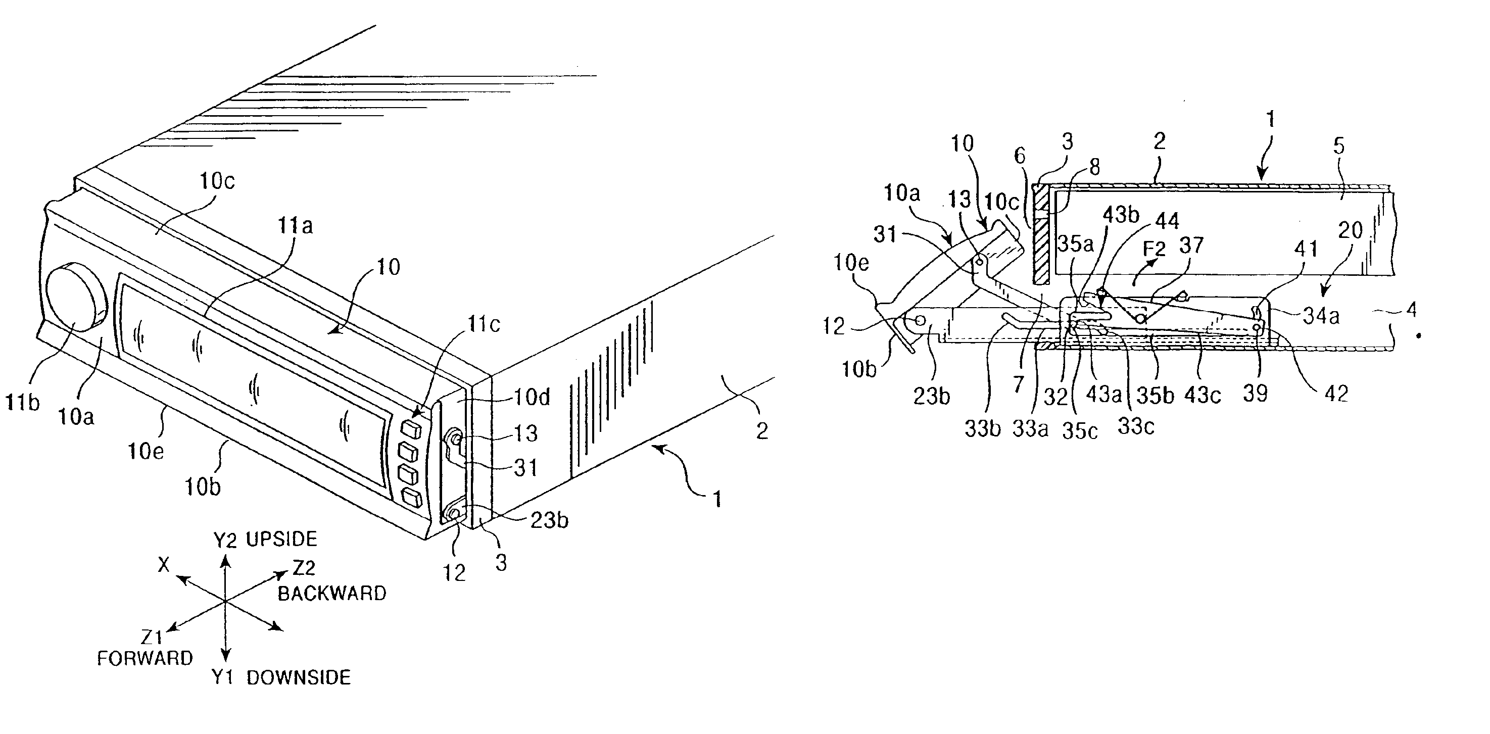
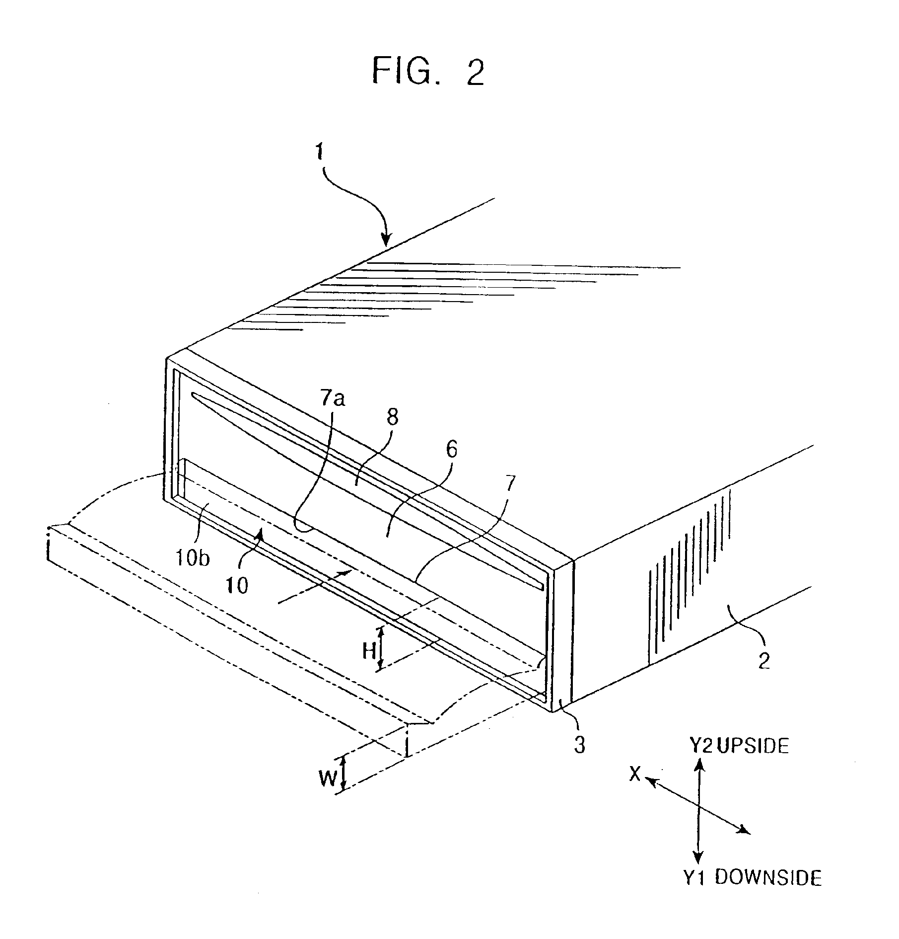
[0011]A vehicle-mounted electronic apparatus of the present invention including a case having an opening on the front surface thereof, a face that moves from an ordinary orientation which is vertical or oblique in front of the case to an accommodated orientation in which the face is accommodated in the case by way of a horizontal orientation which is horizontal in front of said case, a manipulation member disposed on the manipulation surface of the face so as to face forward when the face is in the ordinary orientation, and an orientation variable means for circularly moving the face from the ordinary orientation to the accommodated orientation and for drawing the face into the case from the opening is characterized in that the manipulation member is supported by the face so as to be free to advance and retract so that the amount of projection thereof from the manipulation surface changes and that a retracting mechanism is disposed to retract, when the face is circularly moved from the ordinary orientation to the accommodated orientation, the manipulation member by the relative moving force between a member constituting the orientation variable means and the face so that the amount of projection of the manipulation member from the manipulation surface is reduced.
[0018]In the present invention, the face is circularly moved from the ordinary orientation to the accommodated orientation by the orientation variable means and, at the same time, the manipulation member is retracted making use of the circularly moving force of the face. As a result, when the face is in the ordinary orientation, the manipulation member can be projected in an amount which causes the manipulation member to be manipulated easily, whereas when the face is in the accommodated orientation, the manipulation member retracts so as not to come into contact with the edge of the opening at a time the face retracts into the case.

Problems solved by technology

In vehicle-mounted electronic apparatuses, however, when a face is secured to the front surface of a case or disposed in an inclined orientation, the face is located on the front surface of the vehicle-mounted electronic apparatus at all times. Thus, the apparatus can be easily recognized from the outside appearance thereof, which causes a problem that it may be stolen from the passenger compartment.
However, it is difficult to effectively utilize the front surface of the case located on the back side of the face in a wide range.
However, in this structure in which the face is accommodated in the case, there is a possibility that manipulation members such as a rotary knob, a push button, and the like come into contact with the edge of the opening of the case when the face is accommodated in the case.
However, when the size of the gap is increased or the cut-out is made, the opening cannot be sufficiently closed at a time the face is accommodated in the case.
Further, the gap or the cut-out appears on the front surface of the case in a state in which the face is accommodated, whereby the outside appearance of the case is spoiled.
Furthermore, when the size of projection of the manipulation members projecting from the manipulation surface of the face was reduced, it became difficult to manipulate the manipulation members with fingers when the face is located on the front portion of the case.

Method used


Image

  • Vehicle-mounted electronic apparatus
  • Vehicle-mounted electronic apparatus
  • Vehicle-mounted electronic apparatus

Examples


second embodiment

[0105]FIG. 11 shows the present invention and is an exploded perspective view showing the same portions as those shown in FIG. 4. In the embodiment shown in FIG. 11, a rotary manipulation type part 17 is held in the advancing / retracting member 16 and the manipulation member (rotary manipulation knob) 11b is secured to the manipulation shaft of the rotary manipulation type part 17. Further, the rotary manipulation type part 17 may be rotated by the manipulation member 11b as well as pushed by the depressing force of the manipulation member 11b.

[0106]The manipulation member 11b projects forward from the round hole 10f of the control surface 10a in a state in which the cam member 15 is assembled to the guide portion 10g and the advancing / retracting member 16 is inserted into the cam member 15. Then, when the face 10 takes the horizontal orientation from the ordinary orientation and the cam member 15 is circularly moved by the transmission member 18, the advancing / retracting member 16 ...

third embodiment

[0107]FIGS. 12A and 12B show the present invention. In this embodiment, a manipulation member 11d is disposed in the vicinity of the front edge 10e and extends forward of the control surface 10a of the face 10. This manipulation member 11d is arranged as a push button. Further, a push type manipulation member (for example, a push switch) 52 that is manipulated by the manipulation member 11d is disposed in the face 10 and supported by a movable member 51. The movable member 51 is supported so as to advance and retract with respect to the face 10. Further, the movable member 51 is urged in a retracting direction by a compressed spring 53 at all times.

[0108]As shown in FIG. 12A, when the face 10 is in the ordinary vertical orientation, the movable member 51 is pushed forward by the extreme end 23b1 of the bent piece 23b of the reciprocating member 23 that constitutes the orientation variable means 20, whereby the manipulation member 11d greatly projects from the control surface 10a of ...


PUM


Abstract

A vehicle-mounted electronic apparatus includes a case having an opening on the front surface thereof, a face that moves from an ordinary orientation which is vertical or oblique in front of the case to an accommodated orientation in which the face is accommodated within the case, a manipulation member disposed on the manipulation surface of the face so as to face forward when the face is in the ordinary orientation, and an orientation variable means for circularly moving the face from the ordinary orientation to the accommodated orientation and for drawing the face into the case through the opening. The manipulation member is supported by the face so as to be free to advance and retract, so that the amount of projection thereof from the manipulation surface changes. When the face is circularly moved from the ordinary orientation to the horizontal orientation a retracting mechanism retracts the manipulation member by the relative moving force between the orientation variable means and the face so that the amount of projection of the manipulation member from the manipulation surface is reduced. With the above arrangement, when the face is in its ordinary orientation outside the case, the amount of projection of the manipulation member is set to a large amount L1. When the face circularly moves from the vertical orientation to the horizontal orientation, the retracting mechanism is operated whereby the amount of projection of the manipulation member is reduced to a smaller amount L2. Therefore, when the face having the horizontal orientation is accommodated within the case, the manipulation member does not come into contact with the edge of the opening, and the like.

Description

BACKGROUND OF THE INVENTION[0001]1. Field of the Invention[0002]The present invention relates to a vehicle-mounted electronic apparatus in which a face formed on the front surface of a case can be accommodated in the case in a horizontal orientation.[0003]2. Description of the Related Art[0004]Vehicle-mounted electronic apparatuses used for audio or car navigation are arranged such that a case of a 1DIN size or the like is embedded in a dashboard, an instrument panel, or the like in a passenger compartment, and a face disposed on the front portion of the case appears on a surface which is substantially flush with the dashboard or the instrument panel. Electronic circuits and various types of recording medium drive units, which are accommodated in the case, are controlled by manipulation members disposed on the surface of the face.[0005]In this type of vehicle-mounted electronic apparatus, the face usually is secured to the front surface of a case or circularly movable to an inclined...

Claims


Application Information

Patent Timeline
IPC IPC(8): B60R11/02H04B1/08
CPCB60R11/0205H04B1/082
Inventor SHIBUYA, YASUSHI
Owner ALPINE ELECTRONICS INC
Learn More