
Servo synchronization based on a servo synch mark that conflicts with self-clocking encoding algorithms

a technology of ssm pattern and synchronization, which is applied in the direction of digital recording, recording signal processing, instruments, etc., can solve the problems of data being written to areas, wrong data being read, and the likelihood of ssm pattern being misrecognized in other areas of the servo wedge,

Inactive Publication Date: 2005-08-23
WESTERN DIGITAL TECH INC
View PDF4 Cites 132 Cited by
  • Summary
  • Abstract
  • Description
  • Claims
  • Application Information

AI Technical Summary

Benefits of technology

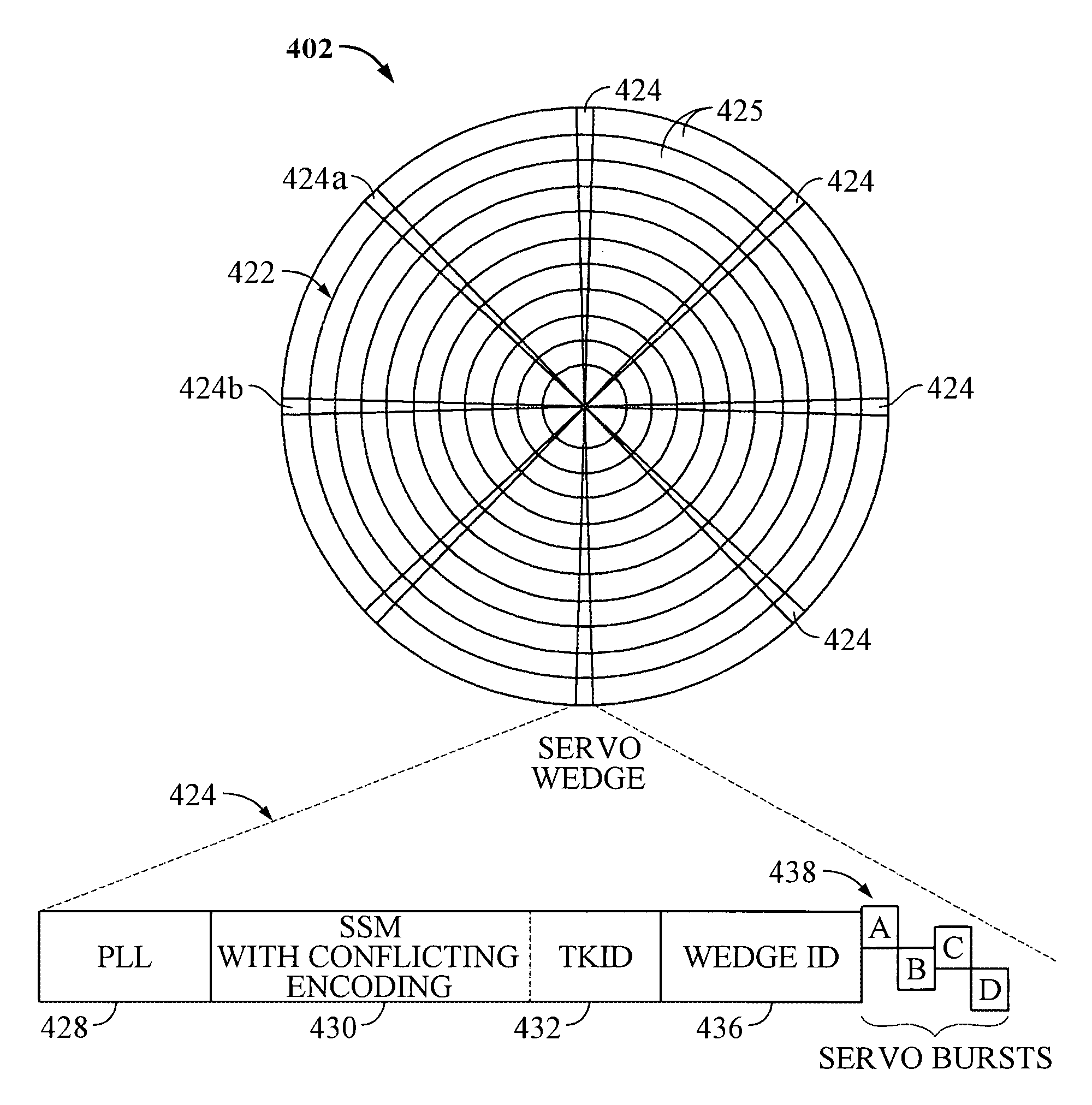
The present invention relates to servo synchronization in a rotating media storage device (RMSD). The invention includes a disk with multiple tracks, each containing data regions and servo wedges. The servo wedges have a servo synch mark (SSM) and a track identifier (TKID) encoded using a self-clocking encoding algorithm. The SSM is also encoded using a second algorithm that conflicts with the self-clocking encoding algorithm of the TKID. This prevents the SSM from being decoded as a portion of the TKID. The invention also includes a synch mark detection circuit and a read / write channel to validate the servo synchronization signal. The technical effect of the invention is to improve the accuracy and reliability of servo synchronization in RMSDs.

Problems solved by technology

However, if the SSM pattern is mistakenly identified in one of the other areas of the servo wedge, read / write operations may be compromised resulting in the wrong data being read, or, data being written to areas of the disk that is not supposed to be.
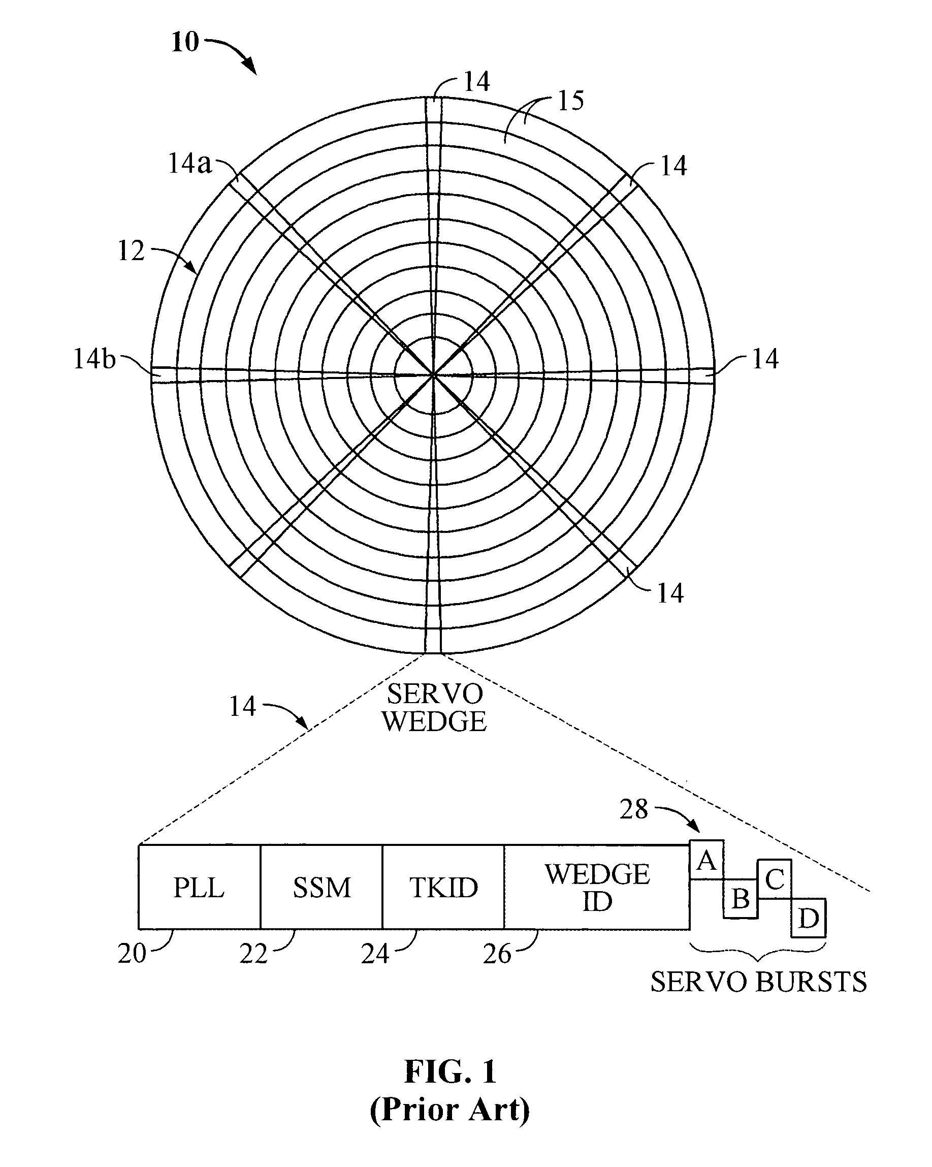
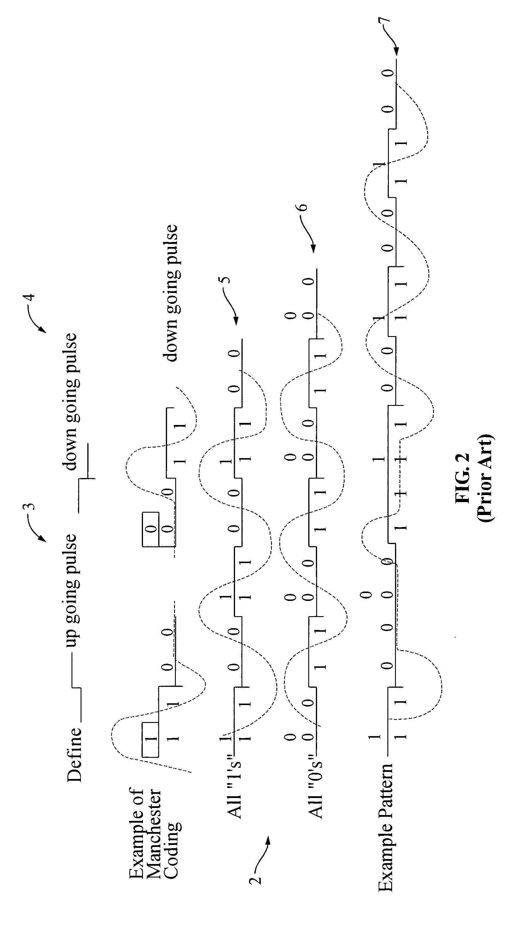
Unfortunately, due to the fact that all of these various servo wedge components utilize the same self-clocking Manchester encoding algorithm, there is a greater likelihood that the SSM pattern will be misrecognized in other areas of the servo wedge.

Method used


Image

  • Servo synchronization based on a servo synch mark that conflicts with self-clocking encoding algorithms
  • Servo synchronization based on a servo synch mark that conflicts with self-clocking encoding algorithms
  • Servo synchronization based on a servo synch mark that conflicts with self-clocking encoding algorithms

Examples


Embodiment Construction

[0030]In the following description, the various embodiments of the invention will be described in detail. However, such details are included to facilitate understanding of the invention and to describe exemplary embodiments for employing the invention. Such details should not be used to limit the invention to the particular embodiments described because other variations and embodiments are possible while staying within the scope of the invention. Furthermore, although numerous details are set forth in order to provide a thorough understanding of the embodiments of the invention, it will be apparent to one skilled in the art that these specific details are not required in order to practice the embodiments of the invention. In other instances details such as, well-known methods, types of data, protocols, procedures, components, electrical structures and circuits, are not described in detail, or are shown in block diagram form, in order not to obscure the invention. Moreover, embodimen...


PUM

PropertyMeasurementUnit
timeaaaaaaaaaa
areasaaaaaaaaaa
circumferenceaaaaaaaaaa

Abstract

Disclosed is a rotatable media storage device (RMSD) that performs servo synchronization based on a servo synch mark (SSM) that conflicts with self-clocking encoding algorithms. The RMSD includes a disk having a plurality of tracks wherein each track comprises a plurality of data regions interspersed between servo wedges. The servo wedges comprise a servo synch mark field including a servo synch mark (SSM) and a track identification field including a track identifier (TKID). The TKID is encoded in accordance with a self-clocking encoding algorithm whereas the SSM is encoded in accordance with a second algorithm that conflicts with the self-clocking encoding algorithm of the TKID. Thus, the SSM is prevented from being decoded as a portion of the TKID.

Description

BACKGROUND OF THE INVENTION[0001]1. Field of the Invention[0002]The present invention relates to rotating media storage devices (RMSDs). More particularly, the present invention relates to an RMSD that performs servo synchronization based on a servo synch mark (SSM) that conflicts with self-clocking encoding algorithms.[0003]2. Description of the Prior Art and Related Information[0004]Computer systems rely on rotating media storage devices (RMSDs), which often employ a moveable head actuator to frequently access large amounts of data stored on the media. One example of an RMSD is a hard disk drive. A conventional hard disk drive has a head disk assembly (“HDA”) including at least one magnetic disk (“disk”), a spindle motor for rapidly rotating the disk, and a head stack assembly (“HSA”) that includes a head gimbal assembly (HGA) with a moveable transducer head for reading and writing data. The HSA forms part of a servo control system that positions the transducer head over a particu...

Claims


Application Information

Patent Timeline
Patent Type & Authority Patents(United States)
IPC IPC(8): G11B20/14G11B27/10G11B27/30
CPCG11B20/1419G11B27/10G11B27/3027G11B2220/20
Inventor KUPFERMAN, HANAN
Owner WESTERN DIGITAL TECH INC
Learn More