
Electric rotating machine and electromagnetic machine and apparatus

a technology of electromagnetic machines and rotating machines, applied in the direction of magnetic circuit rotating parts, magnetic circuit shape/form/construction, instruments, etc., can solve the problems of difficult work, complicated fixing of end coils, and difficult machinery performance of production

Inactive Publication Date: 2005-08-23
KINOSHITA YUKI
View PDF15 Cites 32 Cited by
  • Summary
  • Abstract
  • Description
  • Claims
  • Application Information

AI Technical Summary

Benefits of technology

"The present invention provides a solution for improving the efficiency and output of electric rotating machines and electromagnetic machines. The technical effects include simplifying the winding structure and construction of the iron core, achieving innovative efficiency-up during low output, and realizing various kinds and small productions of iron cores. Additionally, the invention allows for a smooth flow of magnetic field and mutual poles, as well as start and characteristic adjustments using a magnetic body. The invention also includes the use of a skew space and a zigzag shape iron core to achieve the skew effect and avoid magnetic short circuits. Overall, the invention provides a more efficient and effective solution for electric rotating machines and electromagnetic machines."

Problems solved by technology

After the winding assembling work finish, winding end portions are connected and a formation and a fixing of an end coil are complicated and difficult work and become high from a cost aspect and a work process becomes long.
Further, a machinery performance of a production is difficult and much equipment cost for carrying out the above is needed.
Further, in a case of a low voltage and a middle and a large capacity electric rotating machine a diameter of a winding becomes large and then a work performance becomes further worse and a cost-up becomes widely.

Method used


Image

  • Electric rotating machine and electromagnetic machine and apparatus
  • Electric rotating machine and electromagnetic machine and apparatus
  • Electric rotating machine and electromagnetic machine and apparatus

Examples


Embodiment Construction

[0050]Hereinafter, the embodiments for carrying out the invention will be explained by exemplifying an outer rotation type generator referring to the drawings.

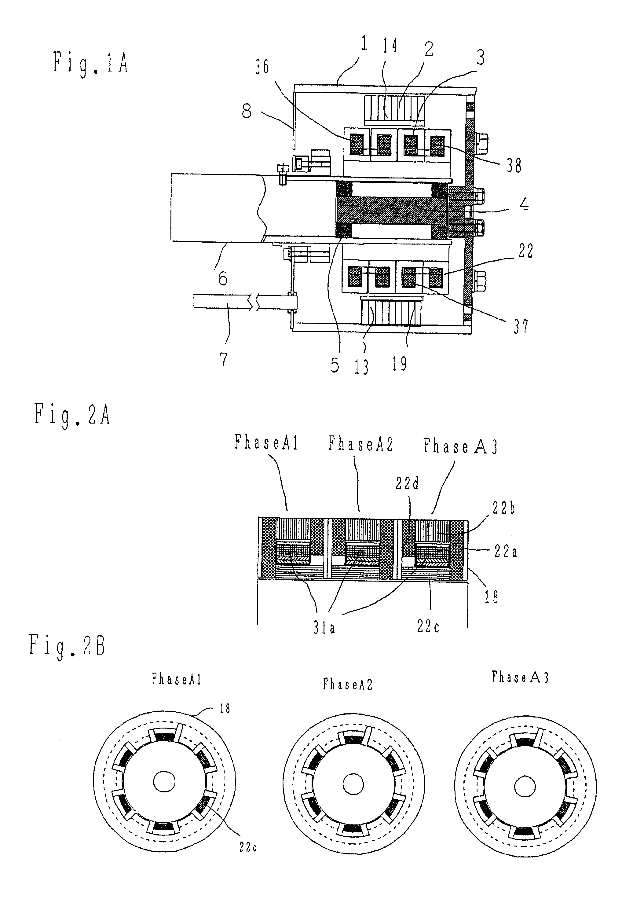
[0051]FIG. 1A is an outer rotation type generator and a cross-sectional structure of the generator according to the present invention having a stator 3 which is constituted by a bobbin type electromagnet and a rotor 2 constituted by a magnet 14.

[0052]When the rotor 2 is driven outside by a power drive source, to coils 36, 37 and 38 etc. wounded in the stator 3, the voltage generates in response to the rotation number, and to an electric power taken-out cord 7 when the loads such as the resistance are connected the current flows and the electric power is supplied. The generation voltage is proportional to the magnetic flux of an air gap formed between the stator 3 and the rotor 2 and also proportional to the rotation number.

[0053]The present invention shows an example of the construction in which the bobbin type structure stato...


PUM


Abstract

To simplify a winding structure of a stator and a rotor of an alternating current electric machine, in a winding a magnetic field formation of a magnetic pole portion is formed with a bobbin structure. In a structural aspect, an eddy current is lessened in an alternating magnetic field. An iron core is formed with a module work and has a reduced metal die cost and it correspond to an alternation in pole number and an iron core having different capacity.

Description

BACKGROUND OF THE INVENTION[0001]1. Technical Field[0002]The present invention relates to an electric rotating machine and an electromagnetic machine and apparatus and further relates to an electric motor, a generator and an electromagnetic machine and apparatus in which magnets and electromagnets are used singly or together with.[0003]A magnetic pole structure, a winding structure and a combination theseof in which an output improvement, and an adjustment improvement, and an efficiency improvement can be improved, and further a productivity of a magnetic pole iron core and an electric work etc. can be made rapid progress.[0004]Further, the present invention relates to a technical field in which an efficiency during a low speed and a low output of the electric rotating machine can be made rapid progress and a heat withstanding performance for forming a compact and a light weight structure can be increased to twice.[0005]2. Prior Art[0006]A member in a stator of a conventional genera...

Claims


Application Information

Patent Timeline
Patent Type & Authority Patents(United States)
IPC IPC(8): H02K1/27H02K3/28H02K1/14H02K21/22H02K3/46
CPCH02K1/145H02K1/2766H02K3/28H02K21/227H02K3/46
Inventor KINOSHITA, YUKI
Owner KINOSHITA YUKI
Learn More