
Combination dehydrator and condensed water dispenser

a condenser and dehydrator technology, applied in the field of dehydrators and water condensers, can solve the problems of global water supply crisis, increased pollution, and increased pollution of water supply in many countries of the world

Inactive Publication Date: 2005-08-23
H20LIQUIDAIR OF FLORIDA +1
View PDF36 Cites 49 Cited by
  • Summary
  • Abstract
  • Description
  • Claims
  • Application Information

AI Technical Summary

Problems solved by technology

There is a worldwide crisis in our potable water supply.
Many countries of the world already have an inadequate water supply.
However, the by-products of such treatment may be toxic and the result in further contamination.
Treated municipal water supplies may be contaminated with lead leading to health problems in drinking such water.
The above patents disclose large and small water condensing units, none realizing the benefits of heated dehydrated air as a source of preserving fruits and vegetables, and none conveniently operate all functions with a remote control.
In Reidy's patents mentioned above, the drain is located on the base of his water generator, a position which makes the drains completely unsuitable for dispensing water unless the machine is placed on legs or mounted in a cabinet.
Poindexter further claims a stainless steel air-cooling coil and collection pan which adds significantly to the cost of manufacturing and does not specify the specific type of stainless steel, 314L, which is required for water handling in production facilities.
One familiar with the art realizes that such heated water would never reach 75° C. A further problem of locating the condenser coil in the storage tank is that it prevents removal of the tank for cleaning without opening the refrigerant system.
Still further maintenance problems arise from the positioning of drains, i.e., there are no external dispensing valves and the drain valves are poorly located for replacing the valves because of the limited access inherent in their location.
Further, Swanson lacks an air filter or a UV disinfecting system.
Further, it has no provision for continuing circulation of water in order to maintain purity, or a thermostat sensor to prevent formation of ice on cooling surfaces of the enclosed atmospheric chilling collection coils.
For example, Reidy (512) shows water production stopping at about 10° C. This limitation occurs because: (a) obtaining condensate is inefficient, (b) condensation is not cost effective at such low temperatures and (c) the evaporator tends to freeze over at lower temperatures.
This limitation also occurs because of the design of the water-generating device using a typical hot-gas bypass deicer which is not computer controlled for temperature / humidity combinations.
When operated over extended periods or in cooler temperatures, the evaporator tends to freeze over due to low flow rate of condensate.
This on / off cycle during cooler temperatures drastically reduces production of water until the compressor eventually stops when the temperature of the incoming air is too low.
Forsberg has a single charcoal filter, which, if hooked up to city water, will clog the filter in a very short time therefore ruining the filter and adding no future protection.

Method used


Image

  • Combination dehydrator and condensed water dispenser
  • Combination dehydrator and condensed water dispenser
  • Combination dehydrator and condensed water dispenser

Examples


Embodiment Construction

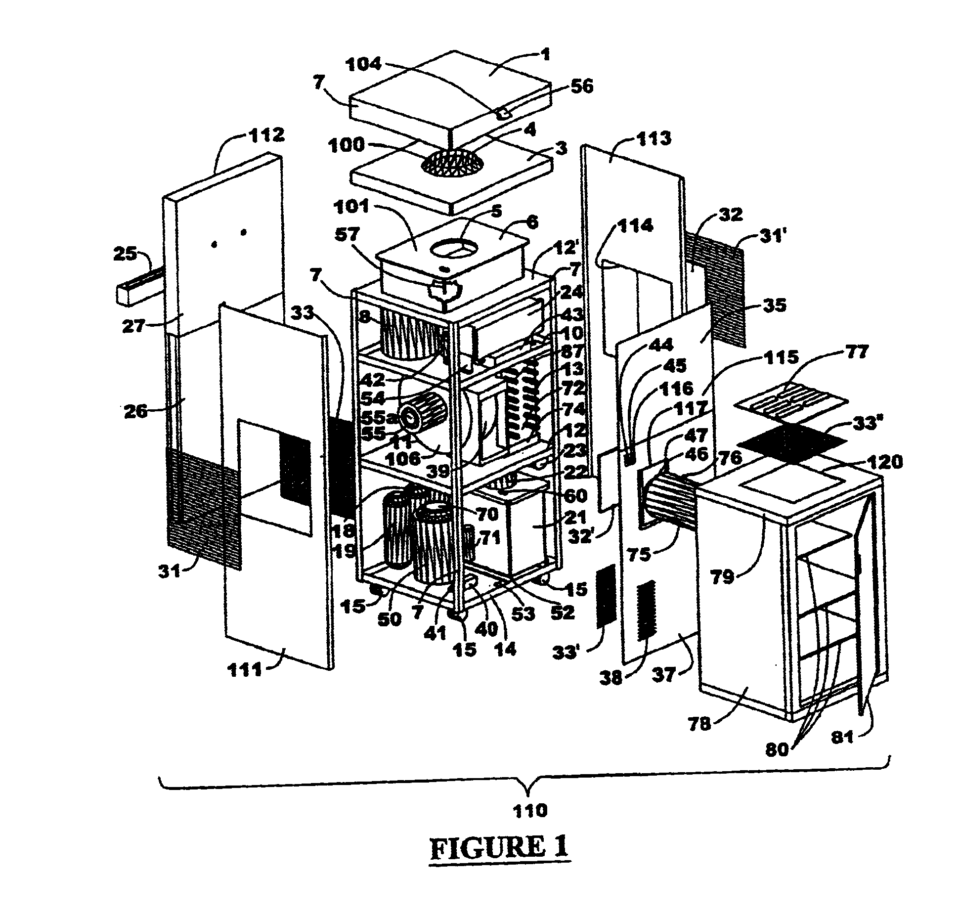
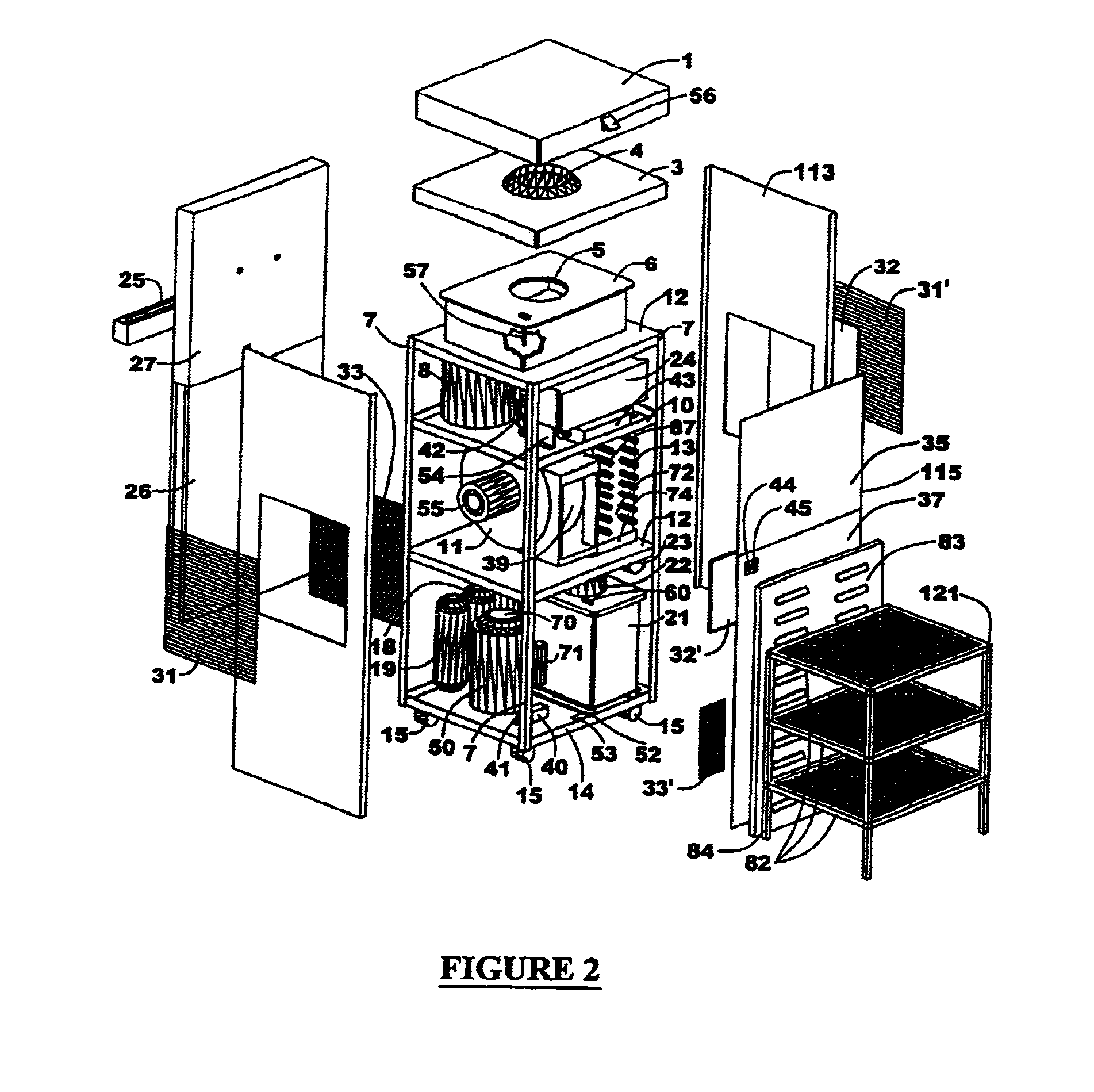
[0033]Referring now to FIG. 1 of the drawings, a combination dehydrator and condensed water dispenser apparatus 110 is shown having a top lid 1, a second lid 3 underneath lid 1, and an upstanding flanged collar 4 surrounding an opening 100 in lid 3 for receiving the top of a bottle of water (not shown) therethrough.

[0034]A holding tank 6 is provided below lid 3 on upper shelf 12′ having a centrally located aperture 5 provided in top wall 101 of tank 6. Lid 1 has downwardly extending sidewalls 102, at least one of which has a flap 56 covering an electric socket 104, such as a 12-volt outlet. A plurality of bio-stimulator probes 89 (see FIG. 3) may be coupled to switch 104 via electric connection 103. Second lid 3 may also have downwardly extending side flaps (not shown).

[0035]As seen in FIG. 1, a portion of tank 6 is cutaway for purposes of illustration to show a magnetic float switch 57 for reasons to be discussed further hereinbelow. Apparatus 110 includes a main upstanding frame 7...


PUM


Abstract

A portable, atmospheric dehydrator and water condenser for dehydrating fruits and vegetables while producing pure atmospheric condensation from humidity found in the air and purifying the water for dispensing and drinking purposes.

Description

[0001]Applicants claim priority to provisional application No. 60 / 296,472 filed Jun. 8, 2001.BACKGROUND OF THE INVENTION[0002]1. Field of the Invention[0003]The invention relates to dehydrators and water condensers, and, more particularly, a combined dehydrator and condensed water dispenser.[0004]2. Related Art[0005]There is a worldwide crisis in our potable water supply. The World Bank has estimated that $600 billion must be invested in water delivery systems. The United Nations has announced a worldwide water shortage and has predicted that, by the year 2010, this crisis could be a catalyst for conflicts and wars.[0006]Many countries of the world already have an inadequate water supply. Usable water supplies have been reduced by pollution and sewage waste.[0007]Various means have been suggested by treating water, such as with chemicals such as chlorine or other halogens. However, the by-products of such treatment may be toxic and the result in further contamination. Treated munici...

Claims


Application Information

Patent Timeline
Patent Type & Authority Patents(United States)
IPC IPC(8): F26B21/00F26B9/00F26B21/08F26B21/06
CPCF26B9/003F26B21/001F26B21/086
Inventor MORGAN, MICHAELMORGAN, JANET
Owner H20LIQUIDAIR OF FLORIDA
Learn More