Eureka AIR delivers breakthrough ideas for toughest innovation challenges, trusted by R&D personnel around the world.

Screwless window frame assembly

a window frame and screwless technology, applied in the field of window frames, can solve the problems of unsightly, relative time-consuming installation, and unsightly screws used to install the frames, and achieve the effect of easy and secure alignment and interconnection, and simple and effective installation

Inactive Publication Date: 2005-08-09
ODL
View PDF11 Cites 51 Cited by
  • Summary
  • Abstract
  • Description
  • Claims
  • Application Information

AI Technical Summary

Benefits of technology

[0005]The aforementioned problems are overcome by the present invention wherein a window frame includes an integral fastening system and an integral alignment system. The frame halves can easily be properly aligned and intersecured during the installation of a doorlight in a door. Preferably, the interconnecting system includes the alignment system.
[0008]The present invention provides a simple and effective window frame that is easily and securely aligned and interconnected. The connectors include positioning structures to ensure proper alignment of the frame halves.

Problems solved by technology

Although these frames enjoy widespread popularity, they can be relatively time consuming to install.
Additionally, the screws used to install the frames, as well as the accompanying screw holes, are unsightly after installation of the frame.
Unfortunately, this Gerard frame, as well as similar screwless window frames, is not without its problems.
One significant problem with the Gerard construction is that it can be difficult to properly align the two frame halves when attempting to permanently secure them.
This increases the time necessary to install the frames.
Once the frame halves are interlocked it is extremely difficult to separate and reposition the frame halves, thus the consumer generally has the options of using the misaligned frame or installing a new system.
The first option is aesthetically unpleasing and can reduce the life of the doorlight by allowing dust and debris into the frame from the misaligned portions.
The latter option is both costly and time consuming.

Method used


Image

  • Screwless window frame assembly
  • Screwless window frame assembly
  • Screwless window frame assembly

Examples


Embodiment Construction

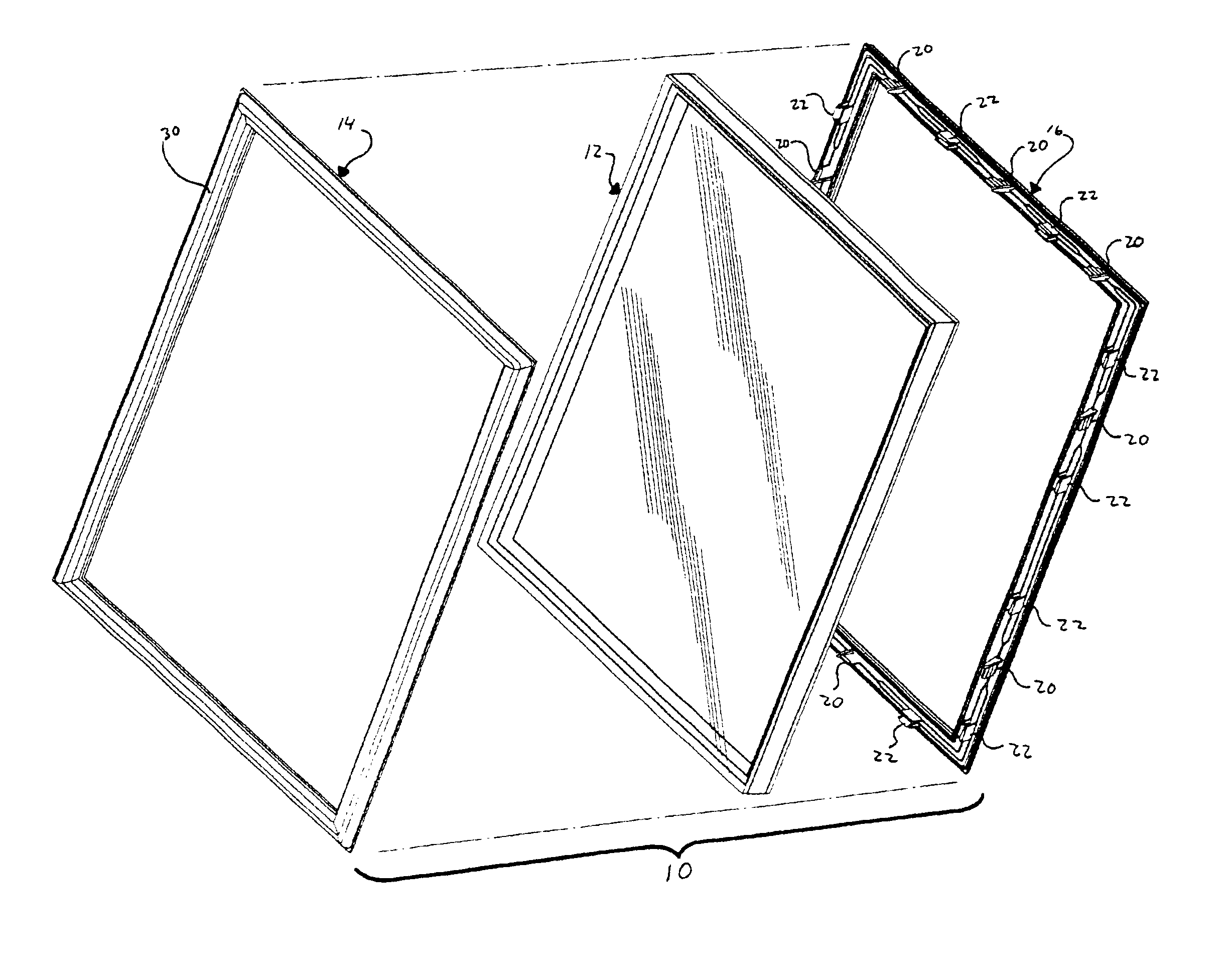
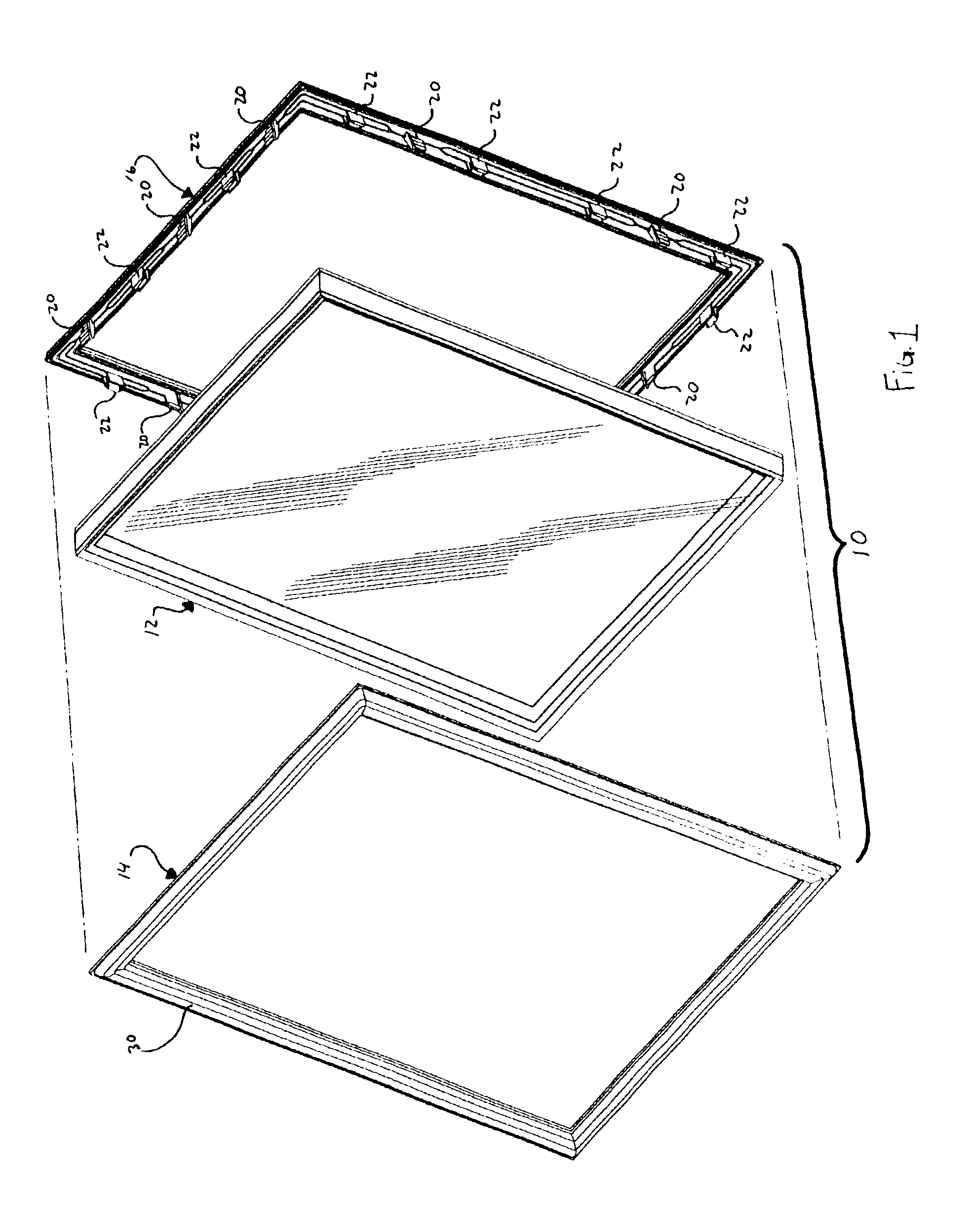
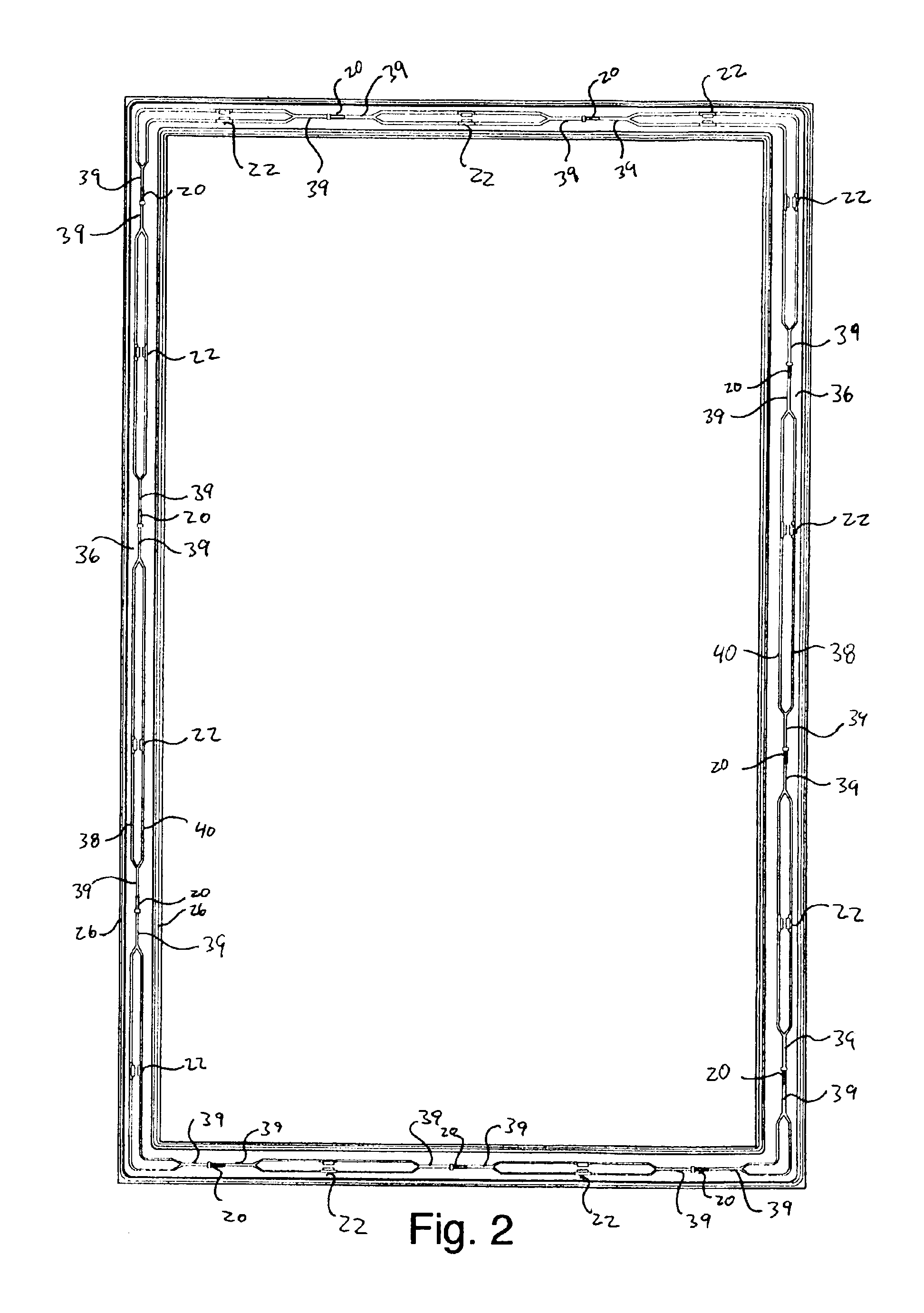
[0019]A doorlight constructed in accordance with a preferred embodiment of the invention is illustrated in the drawings and generally designated 10. With reference to FIG. 1, the doorlight includes an insulated glass assembly 12, a first frame half 14 and a second frame half 16. The first and second frame halves 14, 16 have an interconnecting system including male pieces 20 and female pieces 22 (see FIGS. 4 and 5). These components securely connect the first and second frame halves 14, 16 when the first and second frame halves 14, 16 are pushed together to install them in a door. Each frame half includes gaskets 24 installed along gasket tracks 26. The gaskets 24 seal the glass assembly 12 between the first and second frame halves 14, 16 and seal the first and second frame halves 14, 16 to the door. Though the window frame assembly will be described with reference to a door and doorlight, it is to be understood that the present invention is suitable for use in a variety of settings,...


PUM


Abstract

A window frame including a pair of frame halves having integral fasteners for interconnecting the frame halves. The fasteners include mating barbed connectors that interfit with one another to permanently intersecure the frame halves. The fasteners further include integral cooperating alignment pins and receivers for aligning the fasteners and hence the frame halves. The alignment pins and receivers are laterally offset from the fasteners.

Description

BACKGROUND OF THE INVENTION[0001]The present invention relates to window frames and more particularly to window frames that can be installed without screws or fasteners.[0002]Window frames, such as those used in doorlights, are well known. Doorlight frames in particular, usually include two frame halves—one interior and one exterior—that are screwed together or otherwise interconnected. The frame halves are positioned on opposite sides of an object, such as a door, to support a glazing panel, such as insulated glass. Illustrative doorlight frames are illustrated in U.S. Pat. No. 5,644,881 issued Jul. 8, 1997 to Neilly; U.S. Pat. No. 5,133,168 issued Jul. 28, 1992 to Neilly et al; U.S. Pat. No. 4,920,718 issued May 1, 1990 to Artwick et al; and U.S. Pat. No. 4,021,967 issued May 10, 1977 to Mulder et al. Although these frames enjoy widespread popularity, they can be relatively time consuming to install. Additionally, the screws used to install the frames, as well as the accompanying ...

Claims


Application Information

Patent Timeline
IPC IPC(8): E06B3/58
CPCE06B3/5892
Inventor KROCHMAL, ANDREW R.HUMMEL, BENJAMIN P.
Owner ODL
Why Eureka
Eureka Blog
Learn More