
Belt moving device and image forming apparatus including the same

a moving device and moving plate technology, applied in the field of belt moving devices, can solve the problems of color misregistration, inability to do, and increase the deviation of position with the elapse of time, and achieve the effects of high-quality images, reduced banding, and high-quality positioning control

Inactive Publication Date: 2005-08-02
RICOH KK
View PDF9 Cites 54 Cited by
  • Summary
  • Abstract
  • Description
  • Claims
  • Application Information

AI Technical Summary

Benefits of technology

The present invention is a device that moves belts with high accuracy to prevent speed variations and positional deviation. This invention is useful for image forming apparatuses that need to produce high-quality images without color misregistration.

Problems solved by technology

The problem with a conventional belt moving device is that because it controls the position of the belt on a speed basis, positional deviation increases with the elapse of time.
Particularly, in a color copier configured to sequentially transfer a black, a yellow, a magenta and a cyan toner image to the belt one above the other, the above positional deviation results in color misregister.
More specifically, while position control allows, even when misregister occurs, the belt to follow a target position later, speed control cannot do so.
Further, as for a drive roller for driving the belt, speed control is effective for a frequency as low as the rotation period of the roller, but cannot cope with banding or similar speed variation whose frequency is high.

Method used


Image

  • Belt moving device and image forming apparatus including the same
  • Belt moving device and image forming apparatus including the same
  • Belt moving device and image forming apparatus including the same

Examples


first embodiment

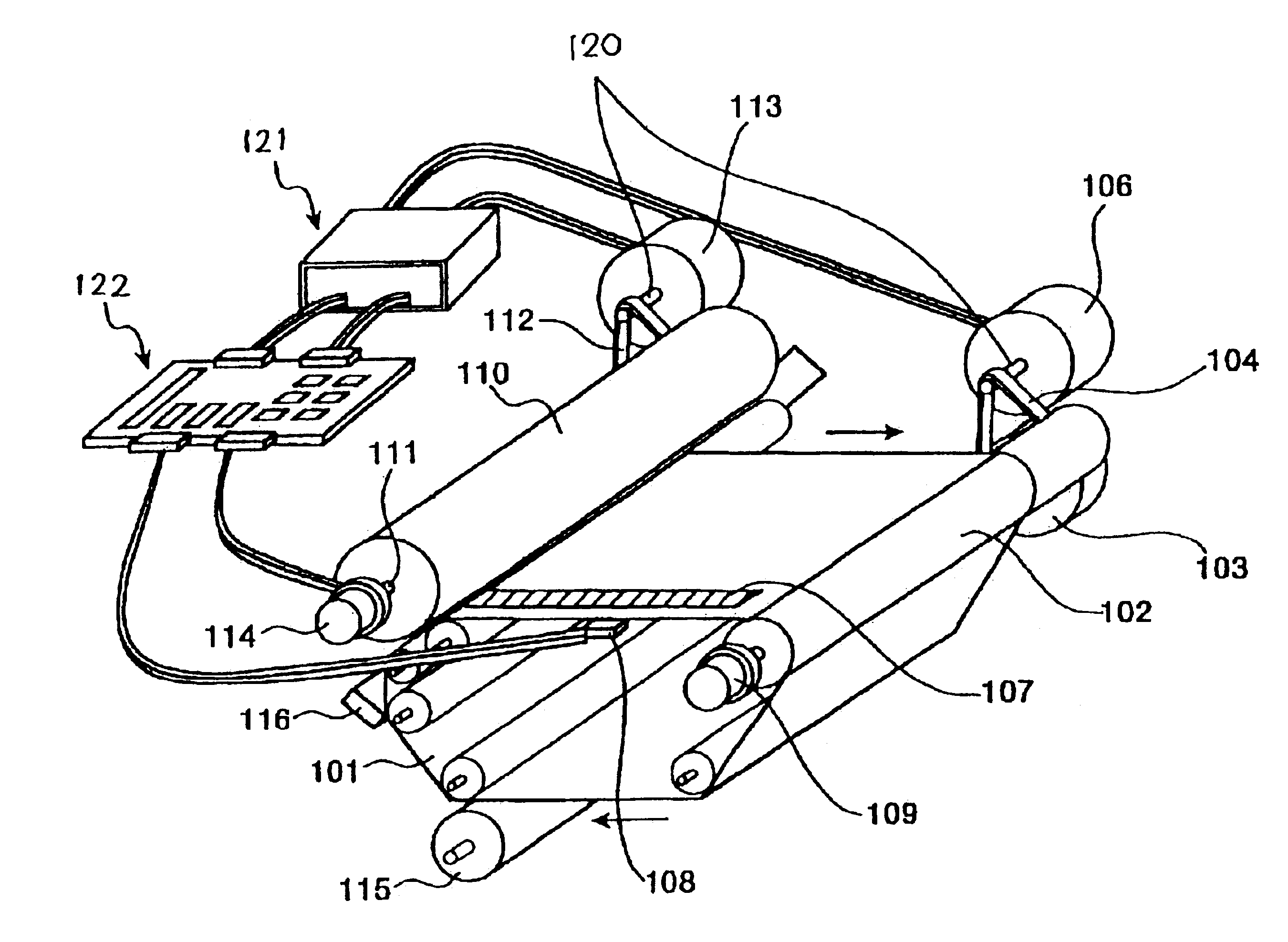
[0043]FIG. 4 demonstrates position control representative of the present invention and executed by the microcomputer 201, FIG. 3. The position control executes correction by using the angle of the drive shaft 102 as a reference. As shown, a command 1 representative of the target surface position of the belt 101 is directly converted to the target position or angle of the drive shaft 102. Comparing means 301 compares a command 2 also representative of the same target position and a surface position of the belt 101. Subsequently, surface position control means 302 produces a difference between the target surface position and the surface position and converts the difference to a target drive shaft position or angle. Adding means 303 adds the target drive shaft position to the command 1, e.g., produces a sum (1 / (shaft radius+belt thickness)).

[0044]Subsequently, another comparing means 304 compares the target drive shaft position or angle and a drive shaft angle. Position control means 3...

second embodiment

[0046]FIG. 5 shows position control representative of the present invention. The position control executes correction, including the correction of the drive shaft 102, by using the angle of the output shaft of the belt motor 106 as a reference. As shown, a command 1 representative of the target surface position of the belt 101 is directly converted to a target motor output shaft position or angle. Comparing means 401 compares a command 2 also representative of the target surface position and a surface position of the belt 101. Subsequently, surface position control means 402 produces a difference between the target surface position and the surface position and converts the difference to a target motor output shaft position or angle. Adding means 403 adds the target motor output shaft position to the command 1, e.g., produces a sum (speed ratio between drive shaft and motor output shaft / (shaft radius+belt thickness)).

[0047]Subsequently, another comparing means 404 compares the target...

third embodiment

[0049]FIG. 6 demonstrates position control representative of the present invention. As shown, comparing means 501 compares a target belt surface position and a belt surface position while surface position control means 502 produces a difference between the two positions. The control means 502 then feeds a current to the belt motor 106 in accordance with the above result, causing the subject of drive to move while following the target position.

[0050]In the illustrative embodiment, the subject of drive is the drive transfer line extending from the belt motor 106 to the surface position of the belt 101, which is the subject of drive. With this configuration, it is possible to control the position of the belt 101 only on the basis of the output of the optical head or sensor 108, i.e., without using the output of the encoder 109.

[0051]FIGS. 7A through 7C show a specific configuration of the belt 101. As shown, the belt 101 is so configured as not to slip on the drive shaft 102. More spec...


PUM


Abstract

A belt moving device of the present invention includes a drive shaft for moving the belt and a drive transfer line for transferring the output torque of a motor to the drive shaft. A marker sensor senses a marker positioned on the belt to thereby determine the position of the belt in the direction of movement. A rotation condition sensor senses the rotation condition of the drive shaft. A first correction information generating circuit generates, based on the output of the marker sensor, correction information for correcting the position of the belt. A second correction information generating circuit generates, based on the output of the rotation condition sensor, correction information for correcting the rotation condition of the drive shaft. A controller controls the movement of the motor in accordance with the correction information output from the first and second correction information generating circuits.

Description

BACKGROUND OF THE INVENTION[0001]1. Field of the Invention[0002]The present invention relates to a belt moving device for controllably moving a belt and more particularly to a belt moving device capable of accurately controlling the position of an intermediate image transfer belt included in a color image forming apparatus, and an image forming apparatus including the same.[0003]2. Description of the Background Art[0004]An intermediate image transfer belt included in a color printer or similar color image forming apparatus has its position controlled by a belt moving device. The problem with a conventional belt moving device is that because it controls the position of the belt on a speed basis, positional deviation increases with the elapse of time. Particularly, in a color copier configured to sequentially transfer a black, a yellow, a magenta and a cyan toner image to the belt one above the other, the above positional deviation results in color misregister. The color misregister c...

Claims


Application Information

Patent Timeline
Patent Type & Authority Patents(United States)
IPC IPC(8): G03G15/01G03G15/16
CPCG03G15/0131G03G2215/0158
Inventor KAMOSHITA, MIKIOKUDO, KOICHI
Owner RICOH KK
Learn More