
Network performance monitoring and restoration based on transmission code violations

a technology of transmission code and network performance monitoring, applied in the field of data and signal communication, to achieve the effect of low cost and low overheard

Inactive Publication Date: 2005-07-12
CIENA
View PDF9 Cites 33 Cited by
  • Summary
  • Abstract
  • Description
  • Claims
  • Application Information

AI Technical Summary

Benefits of technology

The present invention offers a way to monitor and fix problems with computer networks without having to analyze all the data on each individual bit. This saves time and money because it reduces the amount of work needed. It works by looking at specific parts of commonly transmitted signals like 8B/10B.

Problems solved by technology

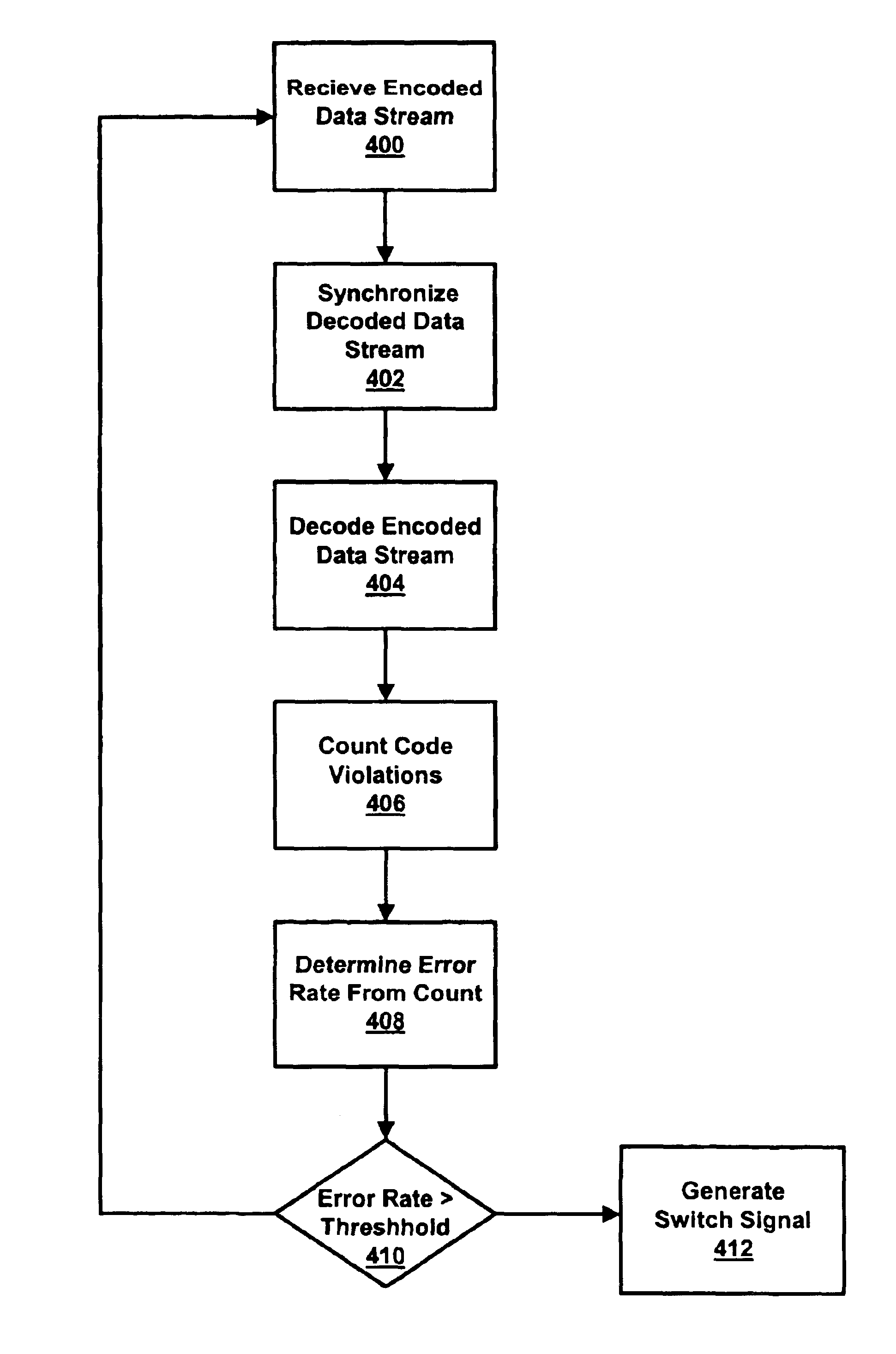
The patent text discusses the need for a system and method to monitor network performance by detecting transmission code violations and triggering network restoration and protection based on the number of violations. The technical problem addressed is the need for a low-cost and low-overhead solution that can be easily integrated into existing communication systems and network topologies.

Method used


Image

  • Network performance monitoring and restoration based on transmission code violations
  • Network performance monitoring and restoration based on transmission code violations
  • Network performance monitoring and restoration based on transmission code violations

Examples


Embodiment Construction

[0018]Although the following description of the present invention refers to 8B / 10B data streams used in IEEE802.3z Gigabit Ethernet transmissions, other networking standards or protocols are equally applicable, including, without limitation 4B / 5B transmission codes used in 100 Mb / s Ethernet and FDDI, and other modulation schemes which use extra code points (e.g., 5×5 QAM).

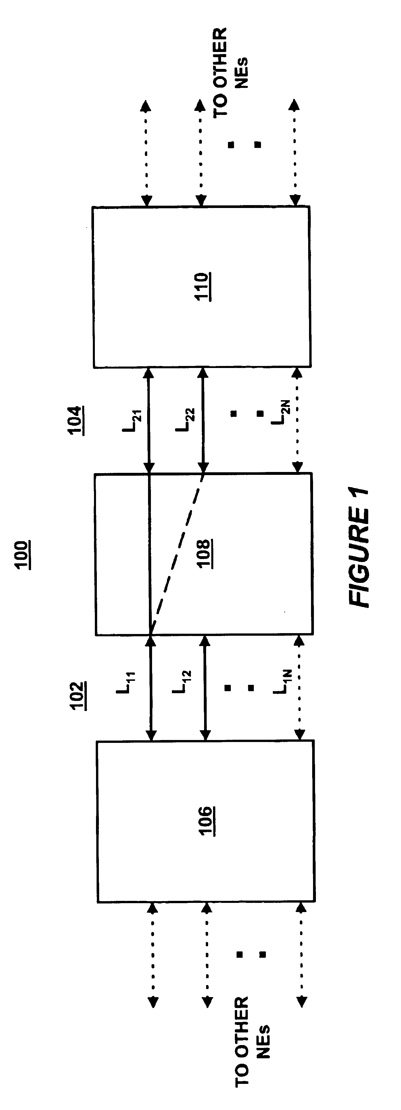
[0019]Referring to FIG. 1, there is shown a block diagram of a communications network 100. Network 100 includes a plurality of interconnected network elements (NEs) 106, 108 and 110, coupled together by a plurality of data links L11, L12, L1N, L21, L22, L2N, as shown in FIG. 1. FIG. 1 makes clear that network 100 may include any number of NEs interconnected in a variety of topologies, including, but not limited to, token ring, star, mesh, bus and other more complex topologies.

[0020]Network 100 includes spans 102 and 104. Span 102 includes NEs 106 and 108 coupled together by full-duplex links L11, L12, L1N and span ...


PUM


Abstract

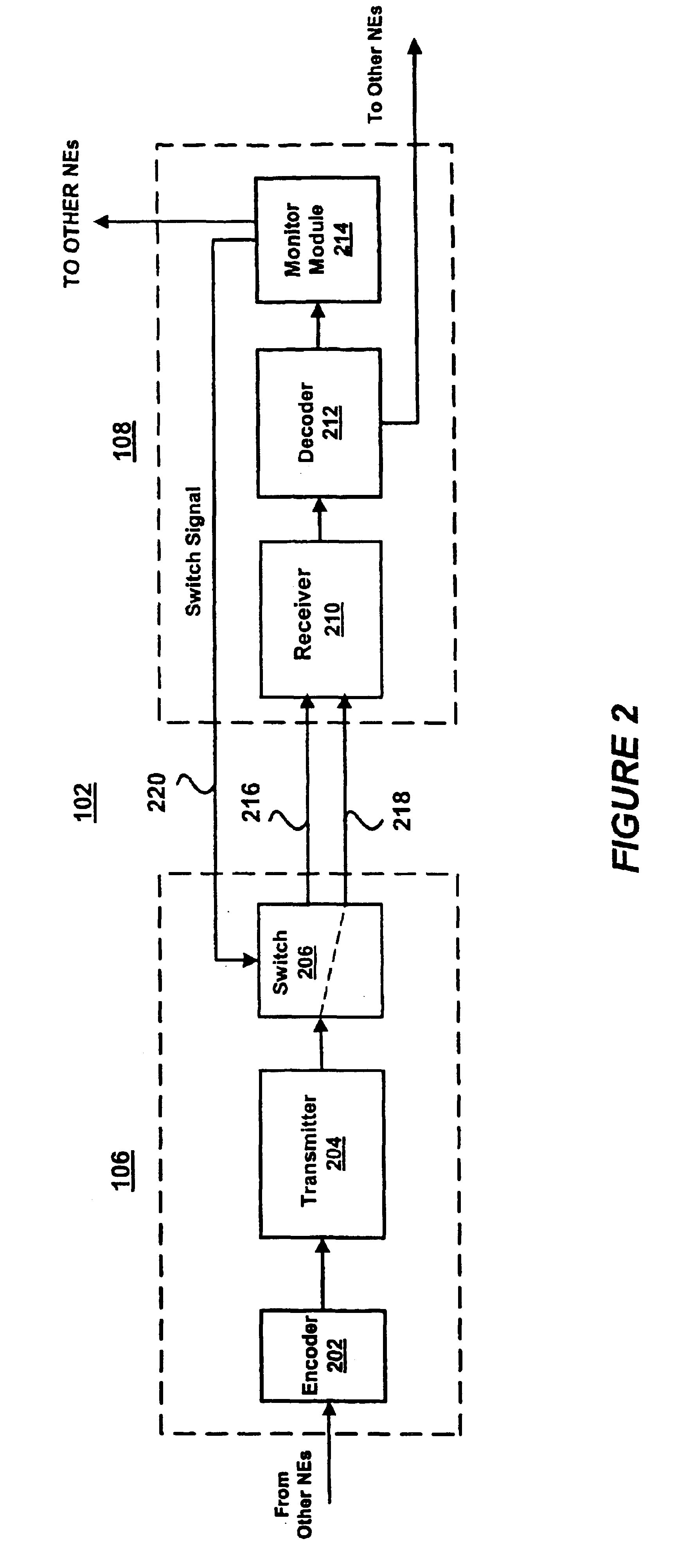
A network element (NE) in a communications network decodes a data stream received over a communication link. Upon synchronization with the data stream, the NE determines a performance metric for the link based on a number of transmission code violations. In response to the performance metric exceeding a predetermined threshold, the NE commands the selection of a different link to carry the data stream via a switch signal. The switching or rerouting of signals may occur between a single pair of NEs (e.g., point-to-point span) or in a more complex topology having a plurality of interconnected NEs.

Description


Claims


Application Information

Patent Timeline
Owner CIENA
Learn More