
Single port single connection VNA calibration apparatus

a single connection, vna technology, applied in the direction of resistance/reactance/impedence, instruments, measurement devices, etc., can solve the problems of time-consuming and labor-intensive calibration process, system errors that are repeatable, and prone to operator errors

Inactive Publication Date: 2005-07-12
ANRITSU CO
View PDF3 Cites 21 Cited by
  • Summary
  • Abstract
  • Description
  • Claims
  • Application Information

AI Technical Summary

Benefits of technology

"The present invention provides an apparatus and method for calibrating a VNA (voltage network analyzer). The calibration module includes a set of reflecting components with known scattering parameters, a switch for connecting the reflecting components, and a memory for storing the known scattering parameters. The calibration module also includes a current source for providing current pulses to the controller module. The controller module includes a processor, a voltage source, and a convertor for converting the current pulses into voltage levels. The method involves measuring scattering parameters, comparing them with the known scattering parameters, and determining calibration values that can be used to correct errors introduced by the VNA. The technical effect of the invention is to provide a reliable and efficient way to calibrate a VNA."

Problems solved by technology

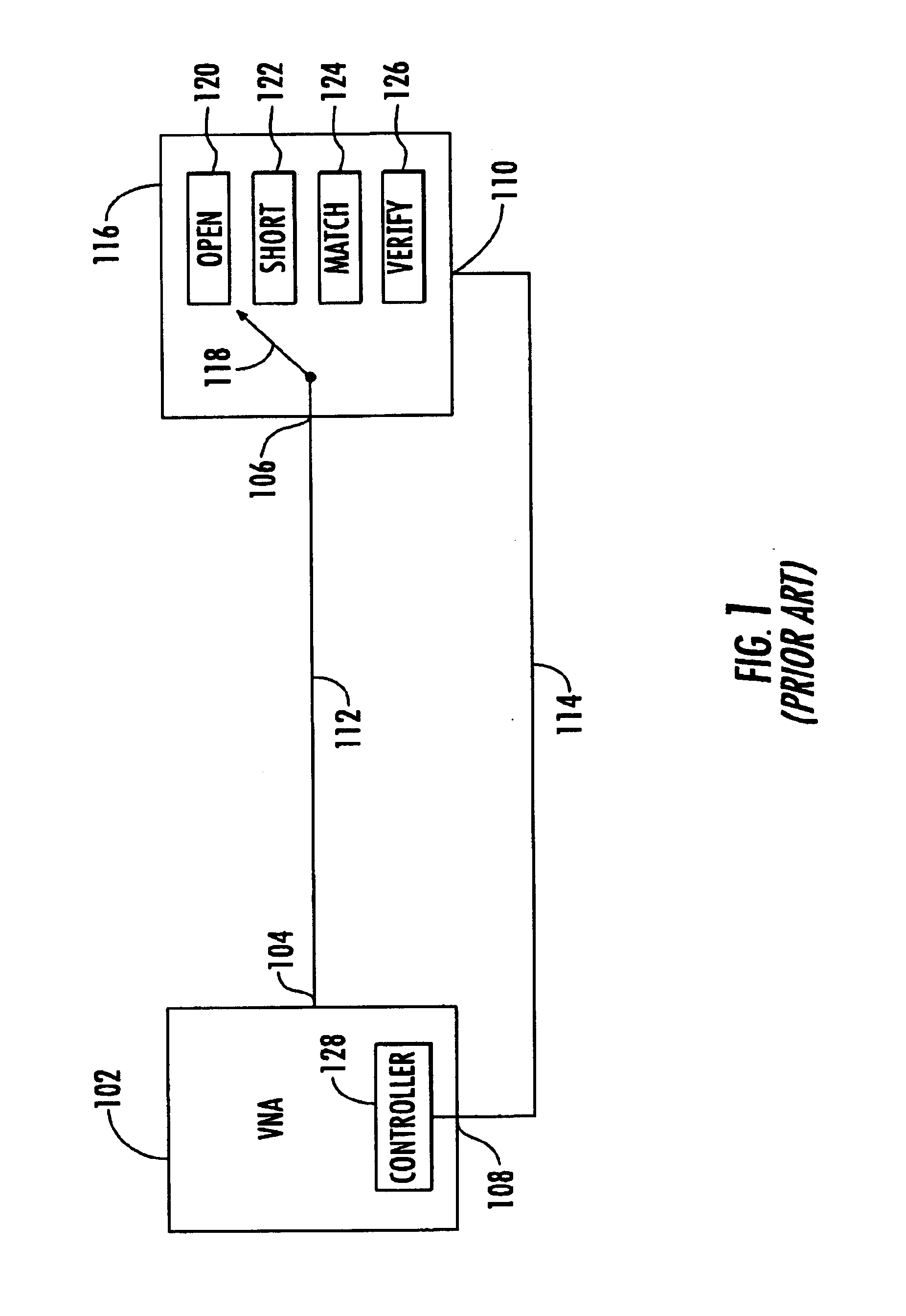
Measurement errors in any vector network analyzer (VNA) contribute to the uncertainty of the device being measured by the VNA.
Random errors are non-repeatable measurement variations due to physical change (e.g., noise and temperature changes) and, therefore, are usually unpredictable.
Systematic errors are repeatable measurement variations in the test setup itself (e.g., directivity, source match, frequency response, and leakage).
In most measurements made on “devices under test” (DUT) with a VNA, the systematic errors are the most significant source of measurement uncertainty.
This calibration process is time-consuming and prone to operator error.

Method used


Image

  • Single port single connection VNA calibration apparatus
  • Single port single connection VNA calibration apparatus
  • Single port single connection VNA calibration apparatus

Examples


Embodiment Construction

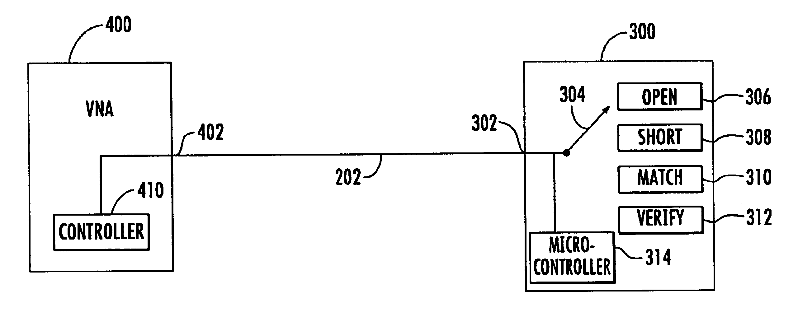
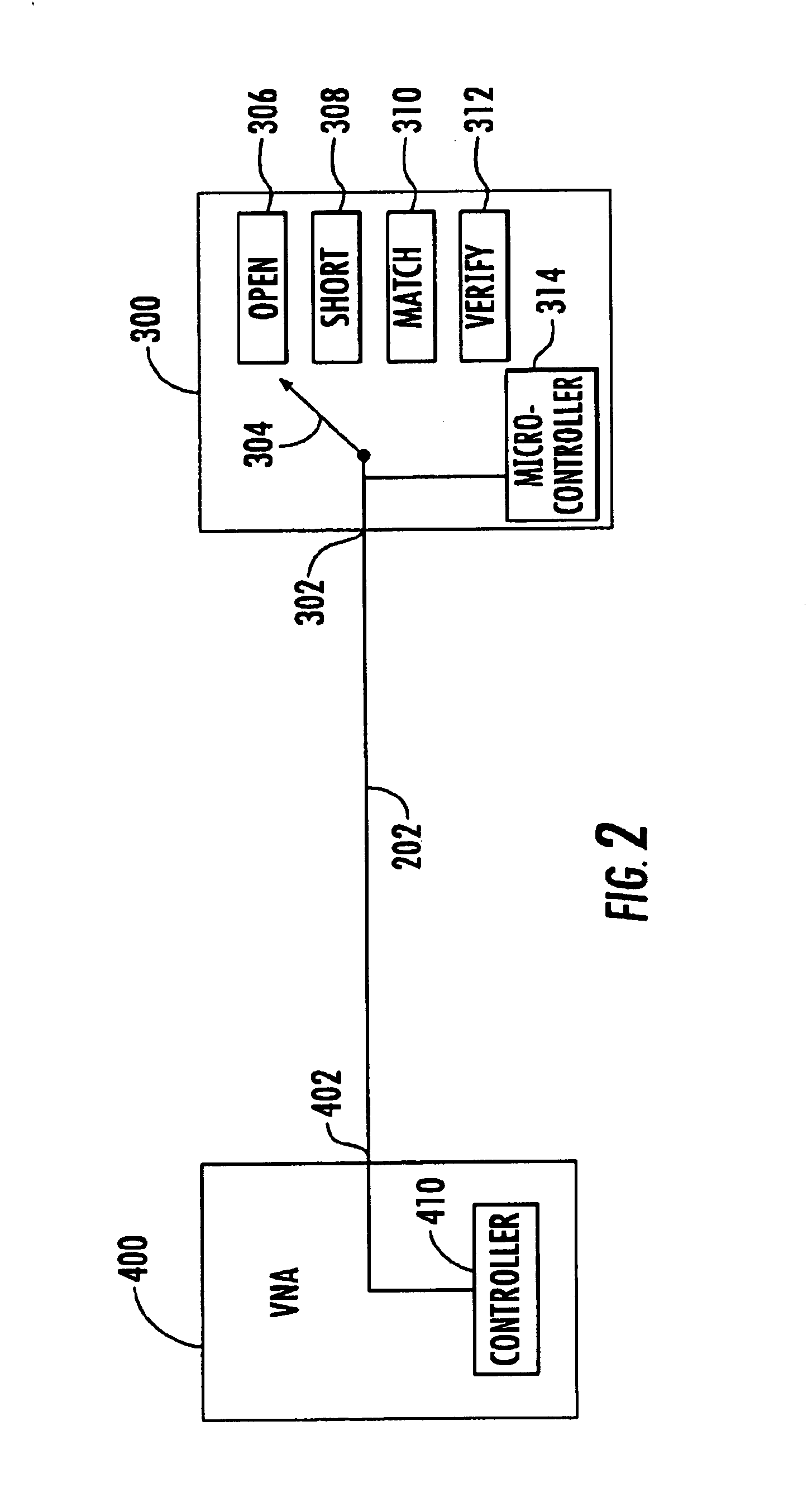
[0024]FIG. 2 depicts a general overview of a VNA calibration apparatus in accordance with the present invention. As shown in FIG. 2, VNA 400 and calibration module 300 communicate through a single RF line 202, which couples RF port 402 with RF port 302. RF line 202 carries control signals from VNA 400 to calibration module 300, and carries data from calibration module 300 to VNA 400. Controller module 410, which in one embodiment is housed inside VNA 400, is connected to RF port 402. Switch assembly 304 couples the reflecting components 306, 308, 310, and 312 to RF port 302.

[0025]The manner of communication between VNA 400 and calibration module 300 will now be discussed. Controller module 410transmits control signals to calibration module 300 through RF line 202. These control signals control the position of switch assembly 304 and the functions of microcontroller 314. Controller module 410 controls the operation of switch assembly 304 by placing four distinct DC voltage levels on ...


PUM


Abstract

A method and apparatus are used to calibration a Vector Network Analyzer (VNA). The method includes providing a calibration module with a single port, providing within the calibration module a set of reflecting components with known scattering parameters, providing control signals to the calibration module through the single port, providing the known scattering parameters to the VNA through the single port, coupling one of reflecting components to the VNA, measuring scattering parameters, and comparing the measured scattering parameters with the known scattering parameters. The apparatus includes a calibration module and a controller module. In one embodiment, the calibration module includes a set of reflecting components, a memory that stores the characterization data, and a current source which sends characterization data in the form of current pulses to the controller module. The controller module includes a voltage source that generates the control signals used by the calibration module.

Description

BACKGROUND OF THE INVENTION[0001]1. Field of the Invention[0002]The present invention relates to calibration of vector network analyzers in general and in particular to a single port, single connection calibration apparatus.[0003]2. Description of the Related Art[0004]Measurement errors in any vector network analyzer (VNA) contribute to the uncertainty of the device being measured by the VNA. By quantifying these errors, their effects can be drastically reduced. Measurement errors in network analysis can be separated into two categories: random errors and systematic errors. Random errors are non-repeatable measurement variations due to physical change (e.g., noise and temperature changes) and, therefore, are usually unpredictable. Systematic errors are repeatable measurement variations in the test setup itself (e.g., directivity, source match, frequency response, and leakage).[0005]In most measurements made on “devices under test” (DUT) with a VNA, the systematic errors are the most...

Claims


Application Information

Patent Timeline
Patent Type & Authority Patents(United States)
IPC IPC(8): G01R27/04G01R35/00
CPCG01R27/04G01R35/005
Inventor BRADLEY, DONALD ANTHONYHONG, KIRBY GARYEN
Owner ANRITSU CO
Learn More