
Vibration inhibiting structure for rotor

a technology of vibration inhibiting structure and rotor, which is applied in the direction of braking discs, slack adjusters, braking elements, etc., can solve the problems that the conventional structure of disc brake devices is not suitable for motorcycles accordingly, and achieve the effect of improving the vibration inhibiting structur

Inactive Publication Date: 2005-07-05
YAMAHA MOTOR CO LTD
View PDF19 Cites 6 Cited by
  • Summary
  • Abstract
  • Description
  • Claims
  • Application Information

AI Technical Summary

Benefits of technology

[0013]A need therefore exists for an improved vibration inhibiting structure for a rotor that has simplicity and can be suitable for a broad frequency range of the natural vibration of the rotor.

Problems solved by technology

The conventionally structured disk brake devices are not suitable for motorcycles accordingly.

Method used


Image

  • Vibration inhibiting structure for rotor
  • Vibration inhibiting structure for rotor
  • Vibration inhibiting structure for rotor

Examples


Embodiment Construction

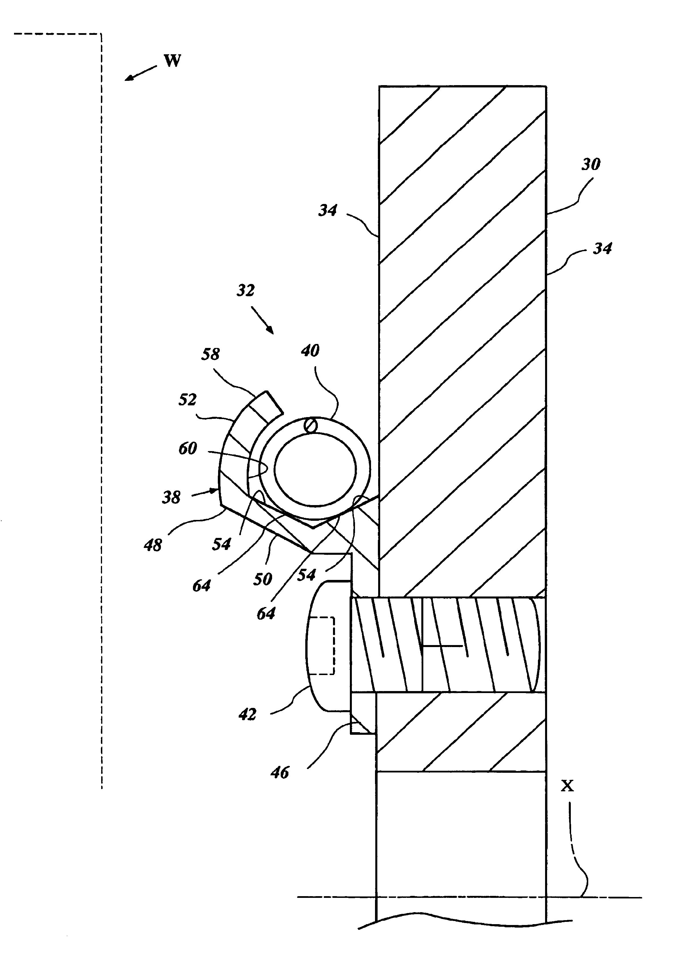
[0025]With reference to FIG. 1, a brake disk 30 having a vibration inhibiting structure 32 is described below. The brake disk 30 has particular utility in the context of a motorcycle, and thus is described in the context of the motorcycle to illustrate one preferred environment of use. The brake disk 30, however, can be used with other types of vehicles such as for, example, all terrain vehicles and automobiles. Furthermore, the vibration inhibiting structure 32 can be applied to various rotors such as, for example, an output shaft of an engine. The vibration inhibiting structures described below, i.e., not only the structure 32 but also all modified or alternative structures, are most suitable for rotors that rotate with speeds under 1,000 rpm.

[0026]The brake disk 30 is affixed to a wheel hub (not shown) of either front or rear wheel W of a motorcycle, or both of the wheels by fasteners such as bolts. The brake disk 30 rotates about the center axis X thereof when the wheel W rotate...


PUM


Abstract

A rotor such as a brake disk for a vehicle has a spring holder that circumferentially extends around an axis of the disk. A coil spring extends around the axis along the spring holder. The spring is loaded onto the spring holder by its own resilience. The spring has a load rate that generates a tension that allows the spring to move circumferentially relative to the spring holder.

Description

PRIORITY INFORMATION[0001]This application is based on and claims priority to Japanese Patent Applications No. 2001-252426, filed Aug. 23, 2001, and No. 2002-139844, filed May 15, 2002, the entire contents of which are hereby expressly incorporated by reference.BACKGROUND OF THE INVENTION[0002]1. Field of the Invention[0003]The present invention is directed to a vibration inhibiting device for a rotor, and more particularly to a vibration inhibiting device for a rotor such as a brake disk.[0004]2. Description of Related Art[0005]Disk brakes are widely used in the automotive arts for braking systems. Recently, more motorcycles have been offered with disk brakes. This type of brake device provides better braking performance for many automotive applications.[0006]Disk brakes, however, can generate a vibrational noise, such as a squeak, during operation. One cause of brake squeak is natural vibration of the brake disk. That is, vibration of a brake disk that occurs in a rotating directi...

Claims


Application Information

Patent Timeline
Patent Type & Authority Patents(United States)
IPC IPC(8): F16D65/12F16D65/00
CPCF16D65/0018F16D65/12
Inventor TANAKA, TOSHIOHAYASHI, MICHIYA
Owner YAMAHA MOTOR CO LTD
Learn More