
Module, nozzle and method for dispensing controlled patterns of liquid material

a liquid adhesive and controlled pattern technology, applied in the direction of liquid spraying apparatus, coatings, pretreated surfaces, etc., can solve the problems of additional expense, spacing consideration, and guide strands, and achieve the effect of improving placement control and repeatable filament orientation

Inactive Publication Date: 2005-06-28
NORDSON CORP
View PDF12 Cites 30 Cited by
  • Summary
  • Abstract
  • Description
  • Claims
  • Application Information

AI Technical Summary

Benefits of technology

[0007]The invention provides an adhesive applicator that results in repeatable filament orientation with improved placement control. Further, the invention provides a predictable relationship between a specific geometric configuration of liquid and air discharge passages and the resulting pattern width and frequency. Thus, the nozzle configuration can be controlled to give a tighter, high frequency filament pattern or a more open, lower frequency filament pattern.
[0011]The inventive concepts apply to dispensing modules having one or more sets of the liquid and air discharge passages. For many applications, it will be desirable to provide a nozzle having multiple side-by-side sets of liquid and air discharge passages with each set configured as described above. In each case, a desirable liquid pattern is achieved by the angular orientation of the air discharge passages with respect to the liquid discharge passage. As a result, different configurations of the air and liquid discharge passage may be made with predictable results.

Problems solved by technology

While this works appropriately in many situations, the strand guides do present additional expense and spacing considerations.

Method used


Image

  • Module, nozzle and method for dispensing controlled patterns of liquid material
  • Module, nozzle and method for dispensing controlled patterns of liquid material
  • Module, nozzle and method for dispensing controlled patterns of liquid material

Examples


Embodiment Construction

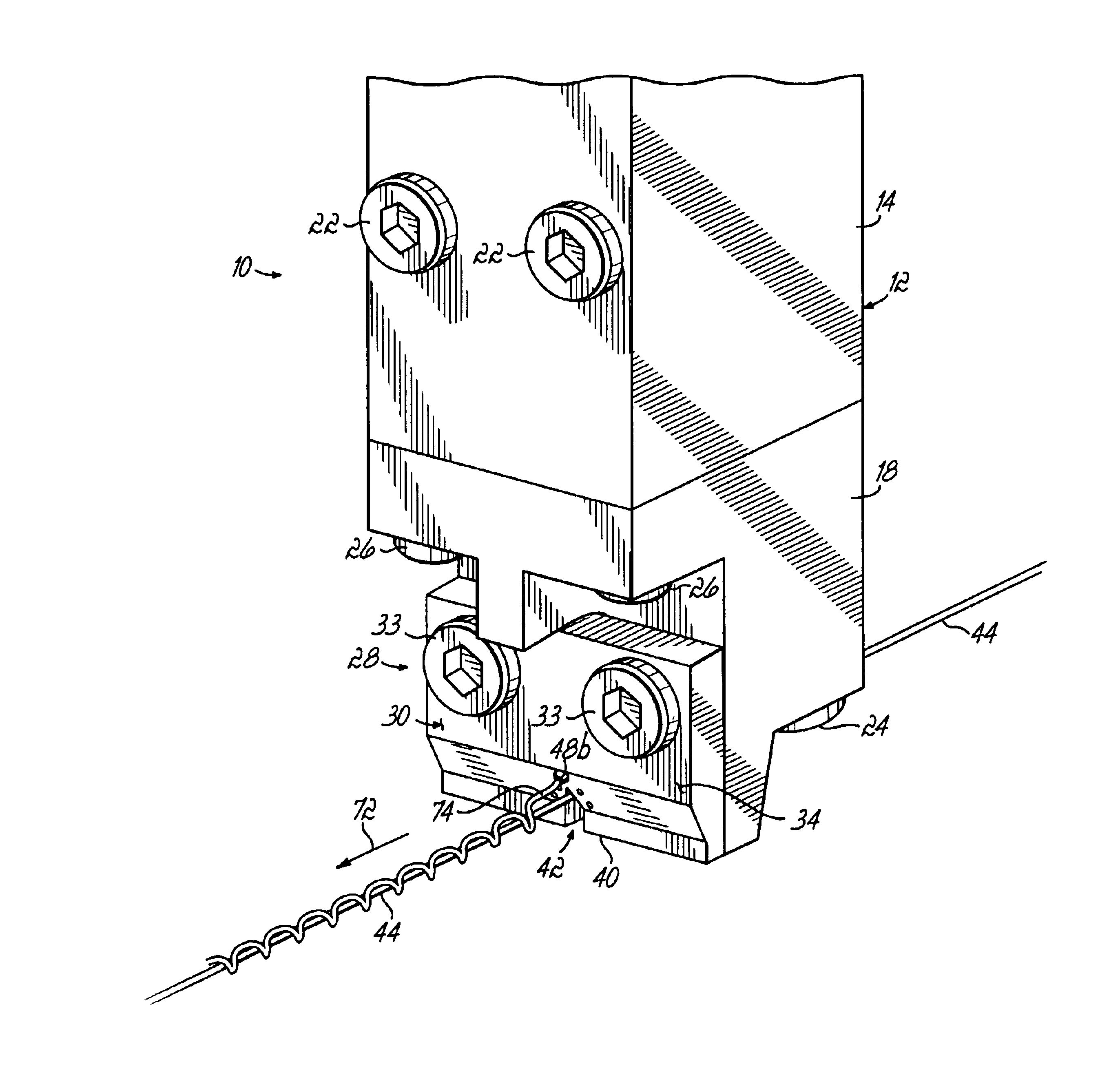
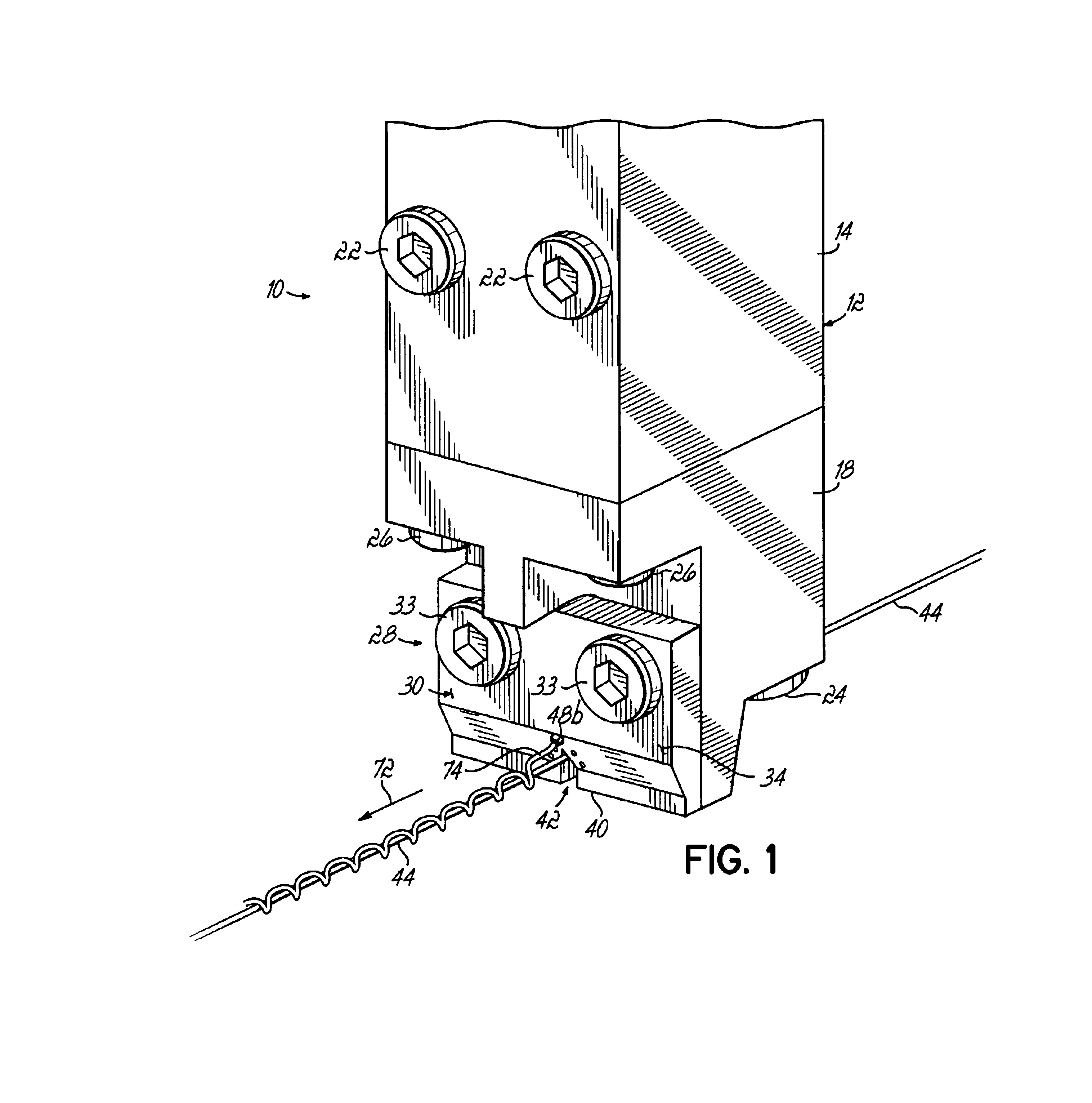
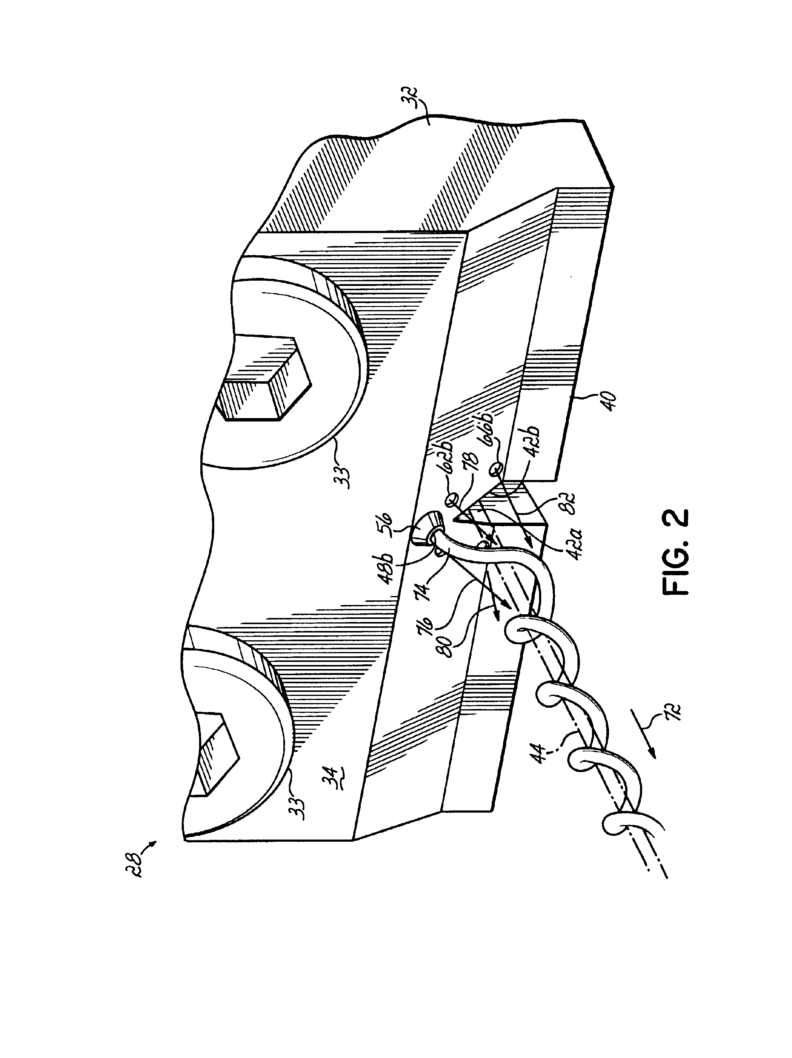
[0028]Referring first to FIGS. 1 and 2, an exemplary dispensing module 10 of the present invention is shown. Dispensing module 10 generally comprises a module body 12 including a central body portion 14 and a lower body portion 18. An upper cap (not shown) is secured to central body portion 14 by fasteners (not shown). Central body portion 14 includes fasteners 22 for securing module 10 to a suitable support, such as a manifold (not shown) which supplies liquid, such as hot melt adhesive, to module 10. Lower body portion 18 is secured to central body portion 14 by respective pairs of fasteners 24, 26. A nozzle assembly or die tip assembly 28 receives liquid and pressurized air from respective supply passages. Nozzle assembly 28 is secured to lower body portion 18 and includes a nozzle or die tip 30. Fasteners 33 secure nozzle 30 to lower body portion 18. Module or applicator 10 is preferably of the on / off type and includes internal valve structure for selectively dispensing liquid, ...


PUM


Abstract

A liquid dispensing module and nozzle or die tip for discharging at least one liquid filament. The nozzle includes a strand guide for guiding a substrate past the nozzle and a frustoconical protrusion disposed on a surface of the nozzle adjacent the notch. A liquid discharge passage extends along an axis through the frustoconical protrusion and forms an acute angle with a machine direction corresponding to movement of the strand past the nozzle. Four air discharge passages are positioned at the base of the frustoconical protrusion. Each of the air discharge passages is angled in a compound manner generally toward the liquid discharge passage and offset from the axis of the liquid discharge passage to create the controlled pattern of liquid material on the strand.

Description

CROSS-REFERENCE TO RELATED APPLICATIONS[0001]This application claims the benefit of U.S. Provisional Application No. 60 / 372,134 filed on Apr. 12, 2002, and the disclosure of which is hereby incorporated by reference herein.FIELD OF THE INVENTION[0002]The present invention generally relates to a liquid material dispensing apparatus and nozzle and, more specifically, to an apparatus and nozzle for dispensing controlled patterns of liquid adhesive strands or filaments.BACKGROUND OF THE INVENTION[0003]Many reasons exist for dispensing liquid adhesives, such as hot melt adhesives, in the form of a thin filament or strand with a controlled pattern. Conventional patterns used in the past have been patterns involving a swirling effect of the filament by impacting the filament with a plurality of jets of air. This is generally known as controlled fiberization or CFJ in the hot melt adhesive dispensing industry. Controlled fiberization techniques are especially useful for accurately covering ...

Claims


Application Information

Patent Timeline
Patent Type & Authority Patents(United States)
IPC IPC(8): B05C5/02B05B7/02B05B7/08B05D3/04B05D1/26
CPCB05C5/0241B05D5/00B05B7/0861B05D3/042B05D2256/00B05D1/26B05B7/10
Inventor CRANE, PATRICK L.HARRIS, MICHAEL W.SAINE, JOEL E.
Owner NORDSON CORP
Learn More