
Device for producing an unvulcanized rubber member for tire manufacturing

a technology of rubber parts and rubber parts, which is applied in the field of unvulcanized rubber parts for tire manufacturing, can solve the problems of deterioration of the external appearance of the fabricated tire, affecting the commercial value of the tire, and achieving the effect of efficient expulsion

Inactive Publication Date: 2005-06-28
BRIDGESTONE CORP
View PDF8 Cites 3 Cited by
  • Summary
  • Abstract
  • Description
  • Claims
  • Application Information

AI Technical Summary

Benefits of technology

[0018]In view of the aforementioned facts, an object of the present invention is to provide an unvulcanized rubber member for tire manufacturing, in which air at the interior of an unvulcanized tire and / or air between the unvulcanized tire and a vulcanizing mold can be efficiently expelled during tire vulcanization, and a device for producing the unvulcanized rubber member for tire manufacturing.
[0021]When the rib-protrusions that extend in the circumferential direction of the tire and the grooves that extend in the radial direction of the tire are provided in the unvulcanized rubber member for tire manufacturing so as to intersect each other, a deficiency in that directions in which air is expelled are limited during vulcanization is mitigated, whereby air remaining at the interior of the green tire and air between the green tire and the vulcanizing mold are allowed to be expelled efficiently.
[0031]If the width of the groove is less than 0.2 mm, the groove will be filled up at the initial stage after starting the tire vulcanization, whereby the effects of air-bleeding is significantly deteriorated. On the other hand, if the width of the groove is more than 1.5 mm, a middle portion of the groove will rise to a shallow depth, whereby the effects of air-bleeding are decreased.

Problems solved by technology

When a molded unvulcanized tire is charged into a vulcanizing mold and then vulcanized, defects referred to as “lights” may appear on the surface of a fabricated tire after vulcanization.
As a result, a problem is caused in that the external appearance of the fabricated tire deteriorates and the commercial value thereof decreases.
Further, when a molded unvulcanized tire is charged into a vulcanizing mold and then vulcanized, a defect may occur in that air remains at the interior of the fabricated tire after vulcanization.
Due to this defect or air void, a problem is caused in that performance and quality of the fabricated tire are deteriorated and the commercial value of the fabricated tire is decreased.
In reality, however, the conventional methods described above have caused such problems as those described below:In the method of (1), that is, in providing a plurality of vent holes, a great deal of expense is required, a lot of spews remain on the surface of the fabricated tire after vulcanization, much time and labor is required to remove the spews, and the external appearance of the fabricated tire is damaged;In the method of (2) of applying the outside coatings, a specific device for the application and considerable expense for coating are necessitated i.e., the coating process thereof is quite time and labor consuming;In the method of (3) of forming linear protrusions or grooves in the tire circumferential direction, air cannot be bled efficiently from the tire surface because irregularities located along the circumferential direction of the vulcanizing mold or located along a radial direction of the unvulcanized tire hinder bleeding, by way of the linear protrusions or grooves, of the air remaining between the unvulcanized tire and the vulcanizing mold during the vulcanization of the tire;In the method of (4) of forming linear grooves in the tire radial direction, in order to bleed the air efficiently, it is necessary to form the grooves at considerably fine pitches, whereby a large device and thus a large space are required, which is costly; andIn the method of (5), it is impossible to conduct efficient bleeding of the air remaining between the tire structuring members by roll-stitching, because most of the tire structuring members for the unvulcanized tire have high tackiness.

Method used


Image

  • Device for producing an unvulcanized rubber member for tire manufacturing
  • Device for producing an unvulcanized rubber member for tire manufacturing
  • Device for producing an unvulcanized rubber member for tire manufacturing

Examples


Embodiment Construction

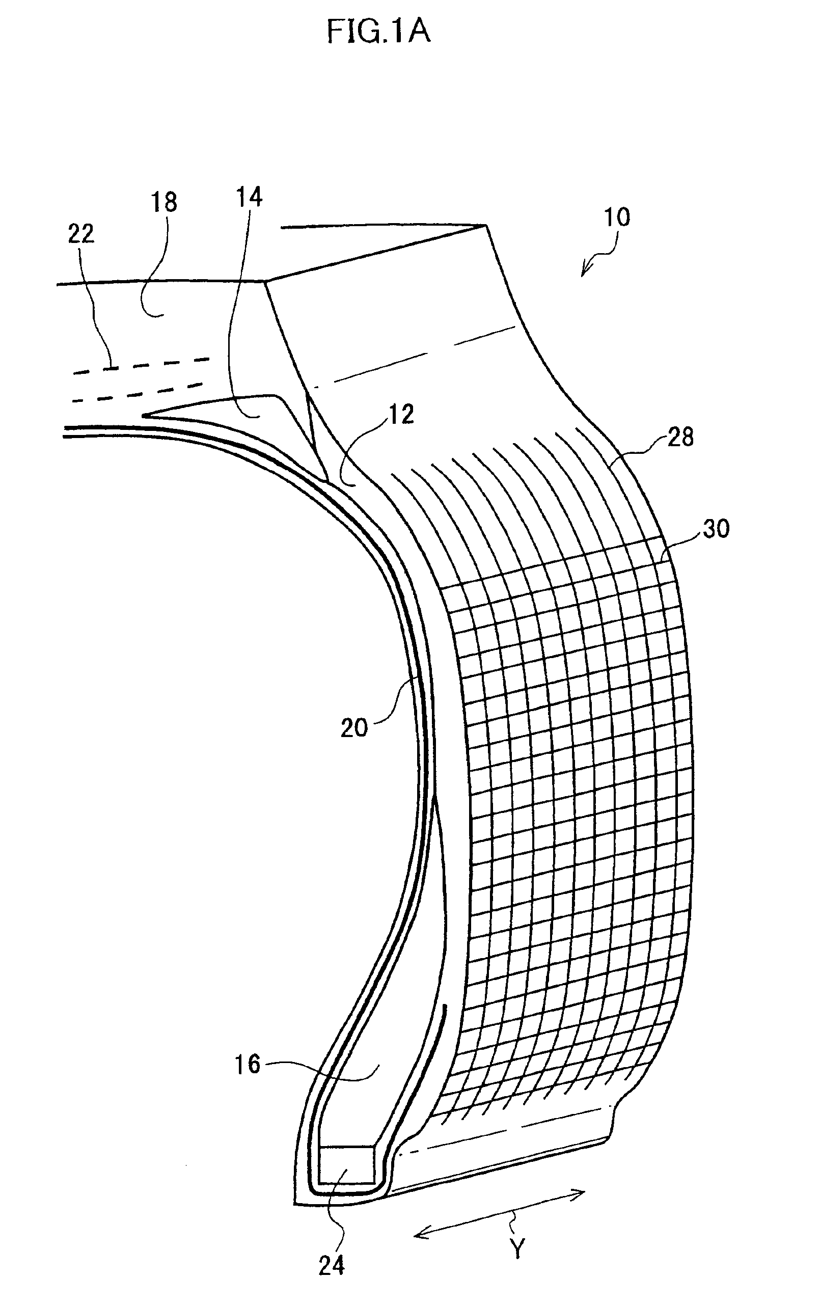
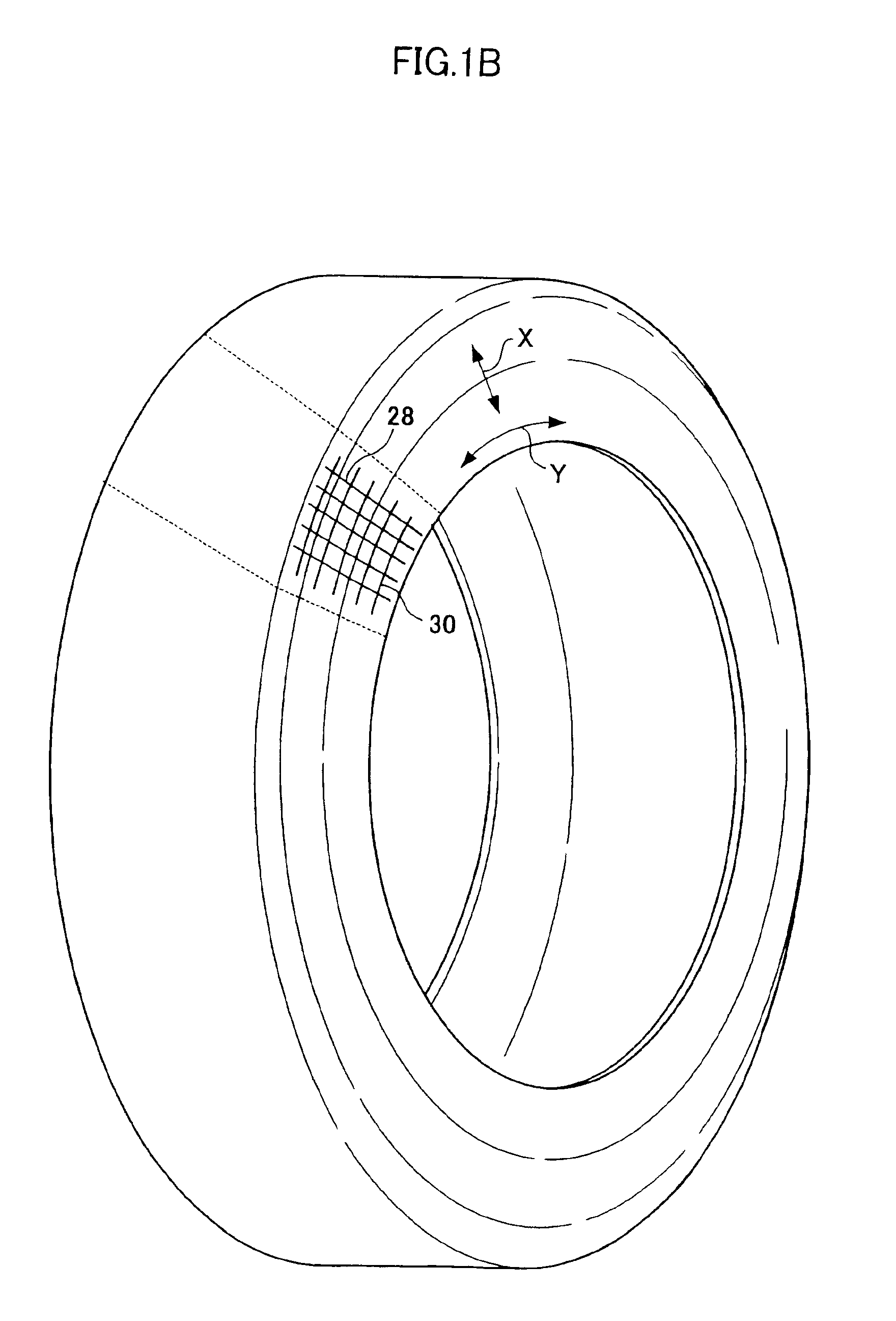
[0045]FIG. 1A shows a cross section of a green tire 10 prior to vulcanization. In FIG. 1A, there are shown a sidewall portion structural member 12, a belt-cushion portion structural member 14, a bead-reinforcement portion structural member (bead filler) 16, a tread portion structural member 18, a carcass 20, a belt 22, and a bead core 24. Further, FIG. 1B is a schematic perspective view of the entire green tire including the portions shown in FIG. 1A (however, only structures necessary to understand FIG. 1A are shown).

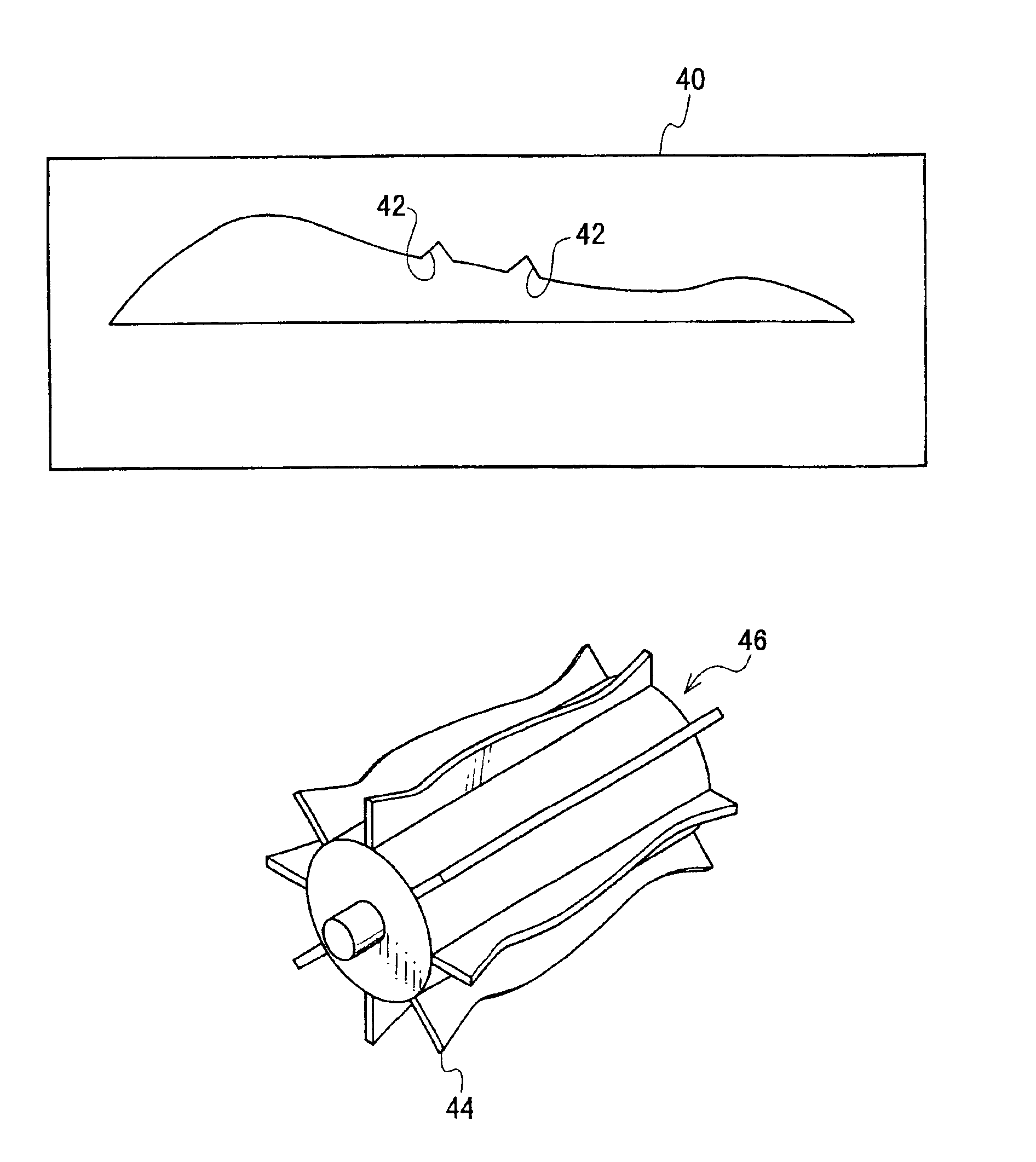
[0046]As shown in FIG. 2, a plurality of grooves 28 which extend along a direction corresponding to a radial direction of a tire (direction of arrow X), and a plurality of rib-protrusions 30 that intersect the grooves 28 and extend in a direction corresponding to a circumferential direction of the tire (direction of arrow Y) are formed on a surface of the sidewall portion structural member 12 formed of unvulcanized rubber (i.e., a surface of the side wall portion struc...


PUM

PropertyMeasurementUnit
widthaaaaaaaaaa
depthaaaaaaaaaa
depthaaaaaaaaaa

Abstract

The present invention provides a device for producing an unvulcanized rubber member for tire manufacturing. The device includes an extruder with a die that extrudes the unvulcanized rubber member to form multiple rib-protrusions that extend in a direction corresponding to a circumferential direction of the tire. A conveying apparatus receives the unvulcanized rubber member and conveys it in the extrusion direction. A roller has an outer surface with protruding portions that form multiple grooves in the unvulcanized rubber member that extend in a direction radial direction of the tire and intersect the rib-protrusions.

Description

BACKGROUND OF THE INVENTION[0001]1. Field of the Invention[0002]The present invention relates to an unvulcanized rubber member for tire manufacturing, a device for producing the unvulcanized rubber member for tire manufacturing, and a method of producing the unvulcanized rubber member.[0003]2. Description of the Related Art[0004]When a molded unvulcanized tire is charged into a vulcanizing mold and then vulcanized, defects referred to as “lights” may appear on the surface of a fabricated tire after vulcanization. As a result, a problem is caused in that the external appearance of the fabricated tire deteriorates and the commercial value thereof decreases. “Lights” are generally produced due to air remaining between the unvulcanized tire and the vulcanizing mold.[0005]Further, when a molded unvulcanized tire is charged into a vulcanizing mold and then vulcanized, a defect may occur in that air remains at the interior of the fabricated tire after vulcanization. Due to this defect or a...

Claims


Application Information

Patent Timeline
Patent Type & Authority Patents(United States)
IPC IPC(8): B29C69/02B29C47/32B29C47/12B29D30/06B29D30/72B29C59/04B29C47/00B29C48/12B29C48/30B29C48/35B29K21/00B29L30/00
CPCB29C47/0038B29C47/32B29D30/72B29C47/00B29C47/003B29C47/0033B29C47/02Y10T428/2457B29D2030/582B29K2021/00B29K2105/246B29L2030/00B29C59/04B29C48/15B29C48/00B29C48/12B29C48/13B29C48/001B29C48/35
Inventor SHIMAZAKI, NOBUYOSHI
Owner BRIDGESTONE CORP
Learn More