Duo-binary encoder and optical duo-binary transmission apparatus

a transmission apparatus and encoder technology, applied in the direction of code conversion, instruments, pulse conversion, etc., can solve the problems of reducing the transmission capacity, affecting the speed of the encoder, so as to reduce or minimize the influence

Inactive Publication Date: 2005-06-21
SAMSUNG ELECTRONICS CO LTD
View PDF6 Cites 4 Cited by
  • Summary
  • Abstract
  • Description
  • Claims
  • Application Information

AI Technical Summary

Benefits of technology

[0020]Another aspect of the present invention relates to a duo-binary encoder which reduces or minimizes any influence due to a data pattern of an input signal by causing a 180° phase shift between data of consecutive ‘0’s and at least one ‘1’ adjacent to the consecutive ‘0’s, even when the number of consecutive ‘0’s of an input data signal is even.

Problems solved by technology

However, the enlargement of transmission capacity is restricted due to severe interference and distortion between channels.
This excessive limitation to the bandwidth causes interference between codes, which thus changes the 2-level binary signal to a 3-level duo-binary signal.
However, according to the prior art, in generating the 3-level data signal by the electric low pass filter, transmission characteristics deteriorate in a manner that depends on the pattern of an input signal.
Therefore, in the case of a high speed data signal, it is difficult to realize a high speed precoder due to time delay and limitation in the operational speed of the XOR gate.
However, such a high speed precoder cannot be realized due to operation speed limitations in the electrical device constituting the encoder.

Method used


Image

  • Duo-binary encoder and optical duo-binary transmission apparatus
  • Duo-binary encoder and optical duo-binary transmission apparatus
  • Duo-binary encoder and optical duo-binary transmission apparatus

Examples


Embodiment Construction

[0033]Hereinafter, embodiments according to the present invention will be described with reference to the accompanying drawings. The same reference numerals are used to designate the same elements as those shown in other drawings. For the purposes of clarity and simplicity, a detailed description of known functions and configuration incorporated herein will be omitted as it may obscure the subject matter of the present invention unclear.

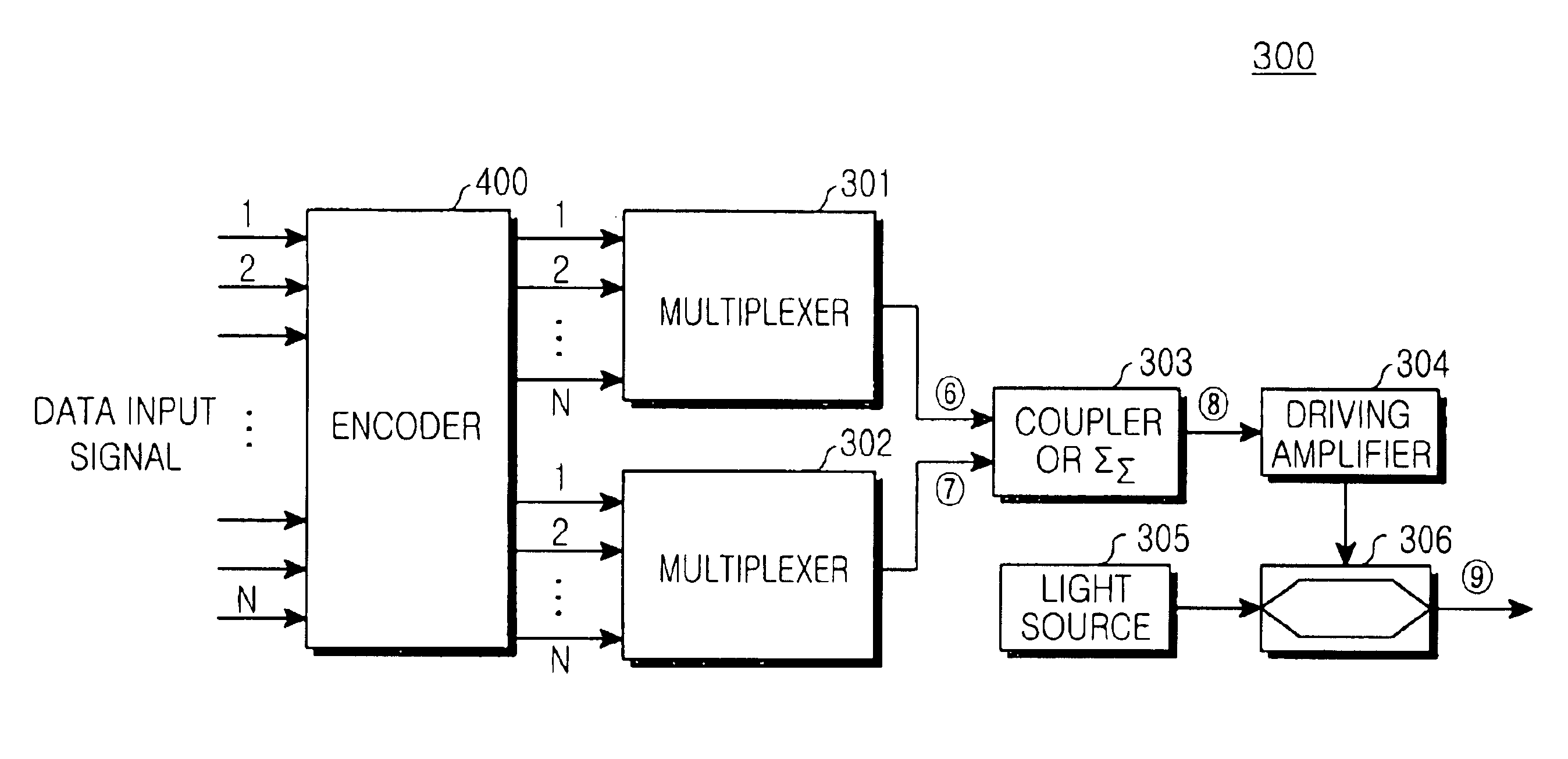
[0034]FIG. 5 is a block diagram showing a construction of an optical duo-binary transmission apparatus 300 according to a first embodiment of the present invention. The optical duo-binary transmission apparatus 300 includes an encoder 400, a first and a second multiplexers 301 and 302, a coupler or an adder 303, a driving amplifier 304, a laser source 305 for outputting a carrier, and a Mach-Zehnder interferometer type optical intensity modulator 306. The encoder 400 encodes N number of data input signals. The first and the second multiplexers 301 an...


PUM

PropertyMeasurementUnit
phaseaaaaaaaaaa
timeaaaaaaaaaa
phasesaaaaaaaaaa

Abstract

An optical duo-binary transmission apparatus using an optical duo-binary transmission method is disclosed. The apparatus includes a duo-binary encoder that performs parallel processing. The duo-binary encoder includes a level change detection unit for detecting that levels of data input signals of N channels input at an nth input of channels change from 0 to 1, or from 1 to 0; a judgment unit for judging whether a number of level changes detected by the level change detection unit is odd or even; and a toggle unit for toggling an output signal of the judgment unit when the number of level change is odd. The encoder also includes an intermediate signal generation unit for determining whether phases of other channels are shifted or not, according to an data input signal on the basis of a predetermined channel of the N channels; and a phase division unit for dividing data into a first data group having non-shifted phases and a second data group which require a phase shift, according to an output signal of the intermediate signal generation unit and the data input signal, and outputting the divided first and second data groups.

Description

CLAIM OF PRIORITY[0001]This application claims priority to an application entitled “Duo-binary encoder and optical duo-binary transmission apparatus using the same,” filed in the Korean Intellectual Property Office on Dec. 1, 2003 and assigned Serial No. 2003-86248, the contents of which are hereby incorporated by reference.BACKGROUND OF THE INVENTION[0002]1. Field of the Invention[0003]The present invention relates to an optical duo-binary transmission apparatus, and more particularly to a parallel processing, duo-binary encoder and an optical duo-binary transmission apparatus using such an encoder.[0004]2. Description of the Related Art[0005]In general, a conventional Dense Wavelength Division Multiplexing (hereinafter, referred to as a DWDM) optical transmission system can transmit an optical signal having multiple channels with different wavelengths through a single optical fiber. The DWDM system can transmit an optical signal regardless of transmission speed. Because of these f...

Claims


Application Information

Patent Timeline
Patent Type & Authority Patents(United States)
IPC IPC(8): G11B20/10H04J3/00H03M5/02H04B10/2507H04B10/2513H04B10/516H04B10/524H04B10/54H04B10/588H04B10/61
CPCH03M5/02H04B10/5167H04B10/5055H04B10/505H04B10/50H04B10/516
Inventor KIM, SUNG-KEELEE, HAN-LIMHWANG, SEONG-TAEK
Owner SAMSUNG ELECTRONICS CO LTD
Why Eureka
Try Eureka