
Articulated artificial finger assembly

a finger and finger technology, applied in the field of artificial fingers, can solve the problems of size and cost, hindering many in need from obtaining expensive electronic prostheses, and creating self-contained electronic finger prostheses,

Inactive Publication Date: 2005-06-21
DIDRICK MEDICAL
View PDF3 Cites 62 Cited by
  • Summary
  • Abstract
  • Description
  • Claims
  • Application Information

AI Technical Summary

Benefits of technology

"The invention is an artificial finger assembly that allows amputees to regain control of the flexion and extension movements of their fingers. The assembly can accommodate a variety of finger amputation cases, including partial and full finger loss. The invention offers a solution for those who need a more human appearance and function than current prosthetic devices. The assembly is composed of a sponge-like filling and can be created using a combination of materials such as silicone and thermoplastics. The invention offers a more efficient and cost-effective solution for replacing missing fingers."

Problems solved by technology

The problems faced with creating electronic artificial fingers for finger amputees are size and cost.
Unfortunately, cost will prevent many in need from obtaining expensive electronic prostheses.
Creating self-contained electronic finger prostheses offer additional difficulties due to the limited space provided.
Finger prostheses commonly are designed for aesthetics more than function and therefore considered somewhat useless in terms of mobility.
This is not true, due to the fact the articulation of the device requires that an articulation bar be retracted from the rear portion of the device.
This is when it becomes clear the device could only be used as a finger when an entire hand or arm is missing.
This still does not begin to describe the mechanics needed to cause movement of the device, which could easily fill the rest of an artificial hand if not forearm.
While the patent described above is of an articulated finger assembly, it offers no benefit to partial or full finger amputations with their hand intact.

Method used


Image

  • Articulated artificial finger assembly
  • Articulated artificial finger assembly
  • Articulated artificial finger assembly

Examples


second embodiment

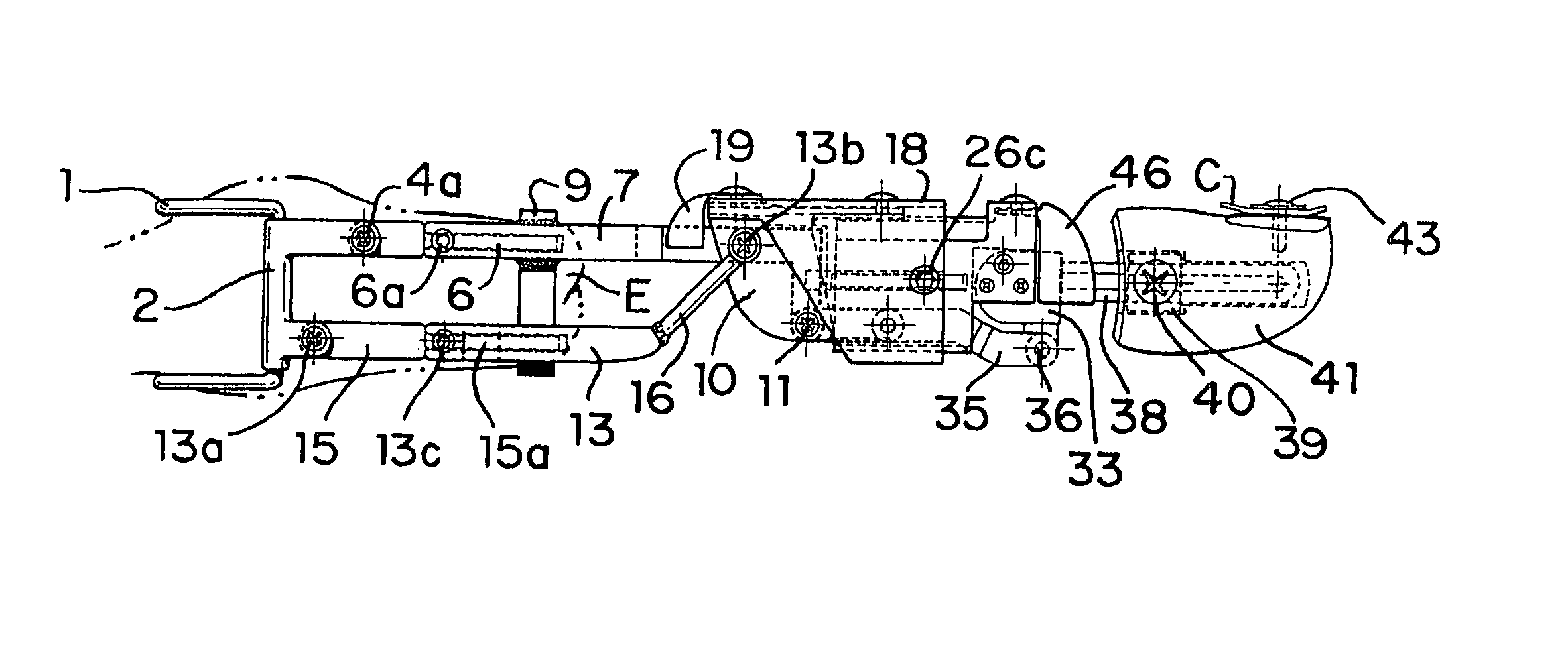
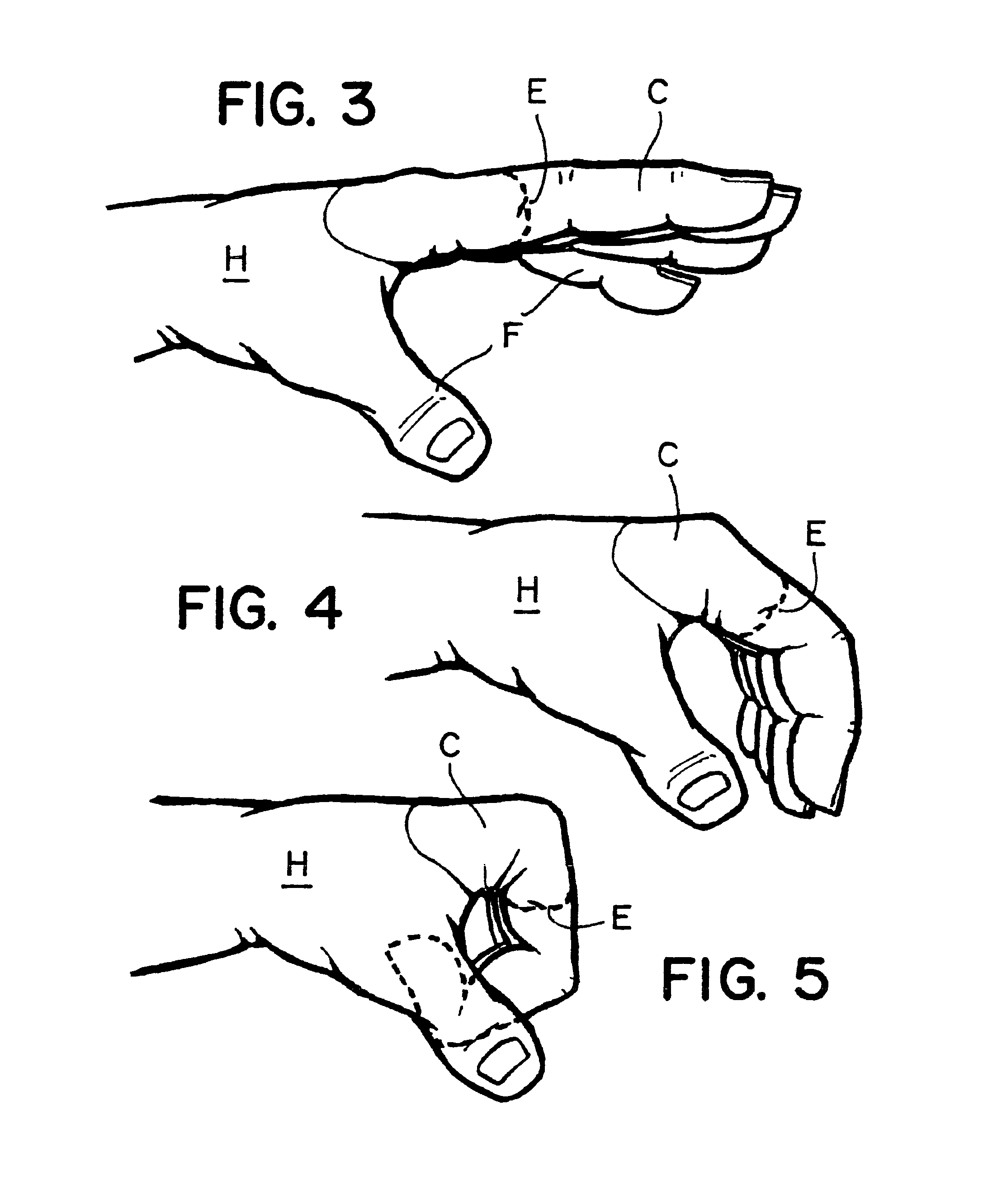
[0024]FIGS. 9-11 shows the operation of the flexion and extension movements of the articulated artificial assembly as demonstrated. The device enables someone to control the motion of an articulated artificial finger with leverage gained from the movement of the remaining portion of an amputated finger or stub. When matrix 1 is in place with the stub inserted through matrix 1 and into ring 9 in a straight position, the articulated device is extended in a pointing position shown in FIG. 9. The matrix 1 remains in place while the stub has freedom to move vertically and horizontally. The articulation of the device can most easily be understood by studying the leverage gained from the forward portion of the upper actuating drive 7, which acts as a lever during articulation. When the finger is extended as in FIG. 9, the leverage gained from the upward pressure on the ring 9, holds the middle phalangeal and phalangeal tip in a straight position. FIG. 10 shows a slightly flexed position of...

embodiment 1

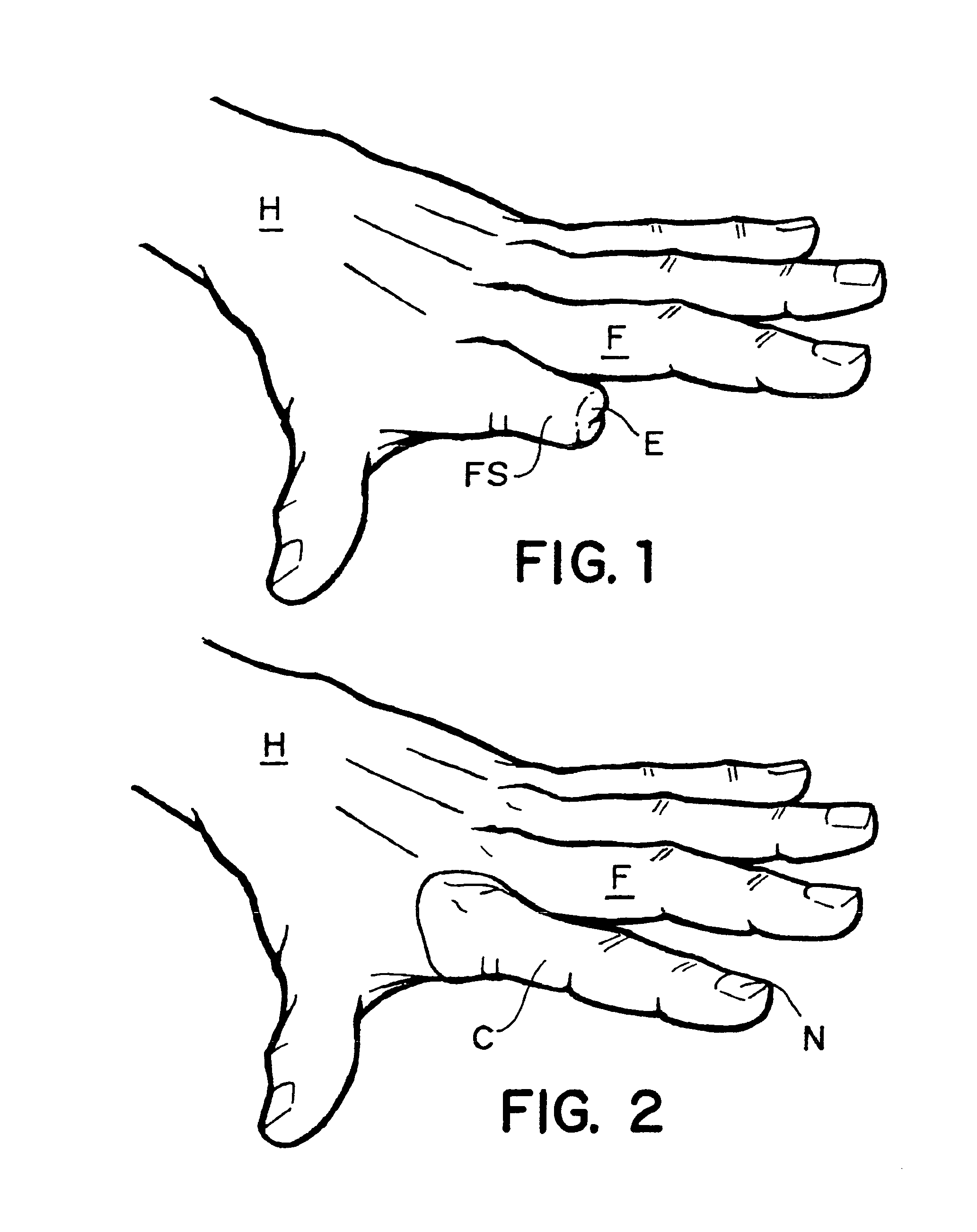
[0025]FIG. 12 illustrates the hand H whereon a finger has been completely amputated leaving the end of the knuckle EK only. Obviously the remaining stub of the finger in the embodiment 1 cannot be used to activate the movement of the artificial finger. Therefore the adjacent finger next to the missing finger is being used for this purpose. Consequently, in FIG. 13 there is a ring 59, which makes this connection shown in subsequent Figures. Also, FIG. 13 shows a supple cover 60 shown in previous figs. as C which is placed over the artificial finger after it is installed including a simulated fingernail 61.

[0026]FIG. 14 illustrates the connection between the normal finger and the mechanism that activates the artificial finger, which is adjacent to the normal finger. To this end the activating ring 59 on the adjacent finger has an extension wire or rod 62 which is fastened to ring 59 by way of welding or soldering and forms a right angle to be explained below. This second embodiment in...


PUM


Abstract

Disclosed is an articulated artificial finger assembly, which can be controlled by the remaining portion of an amputated finger. An adjacent finger is used to manipulate the device when no finger is present. When the stump or adjacent finger begins to bend at the first knuckle, the rest of the device will react to the movements and articulate in the natural manner of a human finger. There are two embodiments shown which, can accommodate a variety of cases. The first embodiment relates to an amputated finger with a portion of the finger remaining. The second is used when a total finger is absent. In either case, the first embodiment uses a ring that is placed over the remaining stub of the finger and the second embodiment a ring is placed over an adjacent finger. The ring, in either embodiment, actuates upper and or lower actuation drives, which are reciprocally and transversely attached to a pivoting block. The pivoting block is fastened to an adjustable middle phalangeal section. The transversely connected upper and lower actuation drives cause the middle phalangeal section to curl under when articulated. The middle phalangeal section is comprised of two main body parts. The first is an outer phalangeal section and the second phalangeal section is placed inside the outer phalangeal section and fastened thereto. A forward fingertip section is pivotally fastened to a forward end of the inner phalangeal section. A forward end of the upper actuating drive is pivotally connected to the forward fingertip section. A supple cover is placed over the device once it is assembled. An inner supple cover is inserted into the device and sealed along the edges of the outer supple cover. To complete the device a screw is inserted into the fingertip, passing through the supple cover and is then hidden by an artificial fingernail placed thereon.

Description

CROSS REFERENCE TO RELATED APPLICATIONS[0001](none)STATEMENT REGARDING FEDERALLY SPONSORED R & D[0002](none)FIELD OF THE INVENTION[0003]This invention pertains to an artificial finger assembly, allowing an amputee to regain control of the flexion and extension movements of an artificial finger. The invention accommodates a variety of finger amputation cases from partial finger loss to entire finger loss. When a portion of the finger is present, the partial fingers movement will articulate the invention to follow the natural bending pattern of a finger. When a finger is entirely missing, the movement of an adjacent finger will control the articulation of the invention.BACKGROUND OF THE INVENTION[0004]Presently the inner construction of an artificial finger is composed of a sponge-like filling. Occasionally, artificial fingers are created with fixable joints as used in action-figure leg joints. These joints provide for stationary positioning of the finger. Presently, technology with s...

Claims


Application Information

Patent Timeline
Patent Type & Authority Patents(United States)
IPC IPC(8): A61F2/50A61F2/58A61F2/00A61F2/80A61F2/78
CPCA61F2/586A61F2/80A61F2002/5001A61F2002/7856A61F2002/502A61F2002/5039A61F2002/5043A61F2002/5018
Inventor DIDRICK, DANIEL DEAN
Owner DIDRICK MEDICAL
Learn More