
Safety catch mechanism of nail guns

a safety catch and nail gun technology, applied in the field of nail gun assembly, can solve the problems of affecting the life of the nail gun, damage to the nail gun, and continuous shooting of nails, so as to prevent the structure of the firing device and the firing pin from being damaged, and shorten the life of use

Inactive Publication Date: 2005-06-21
NAILERMATE ENTERPRISE
View PDF7 Cites 58 Cited by
  • Summary
  • Abstract
  • Description
  • Claims
  • Application Information

AI Technical Summary

Benefits of technology

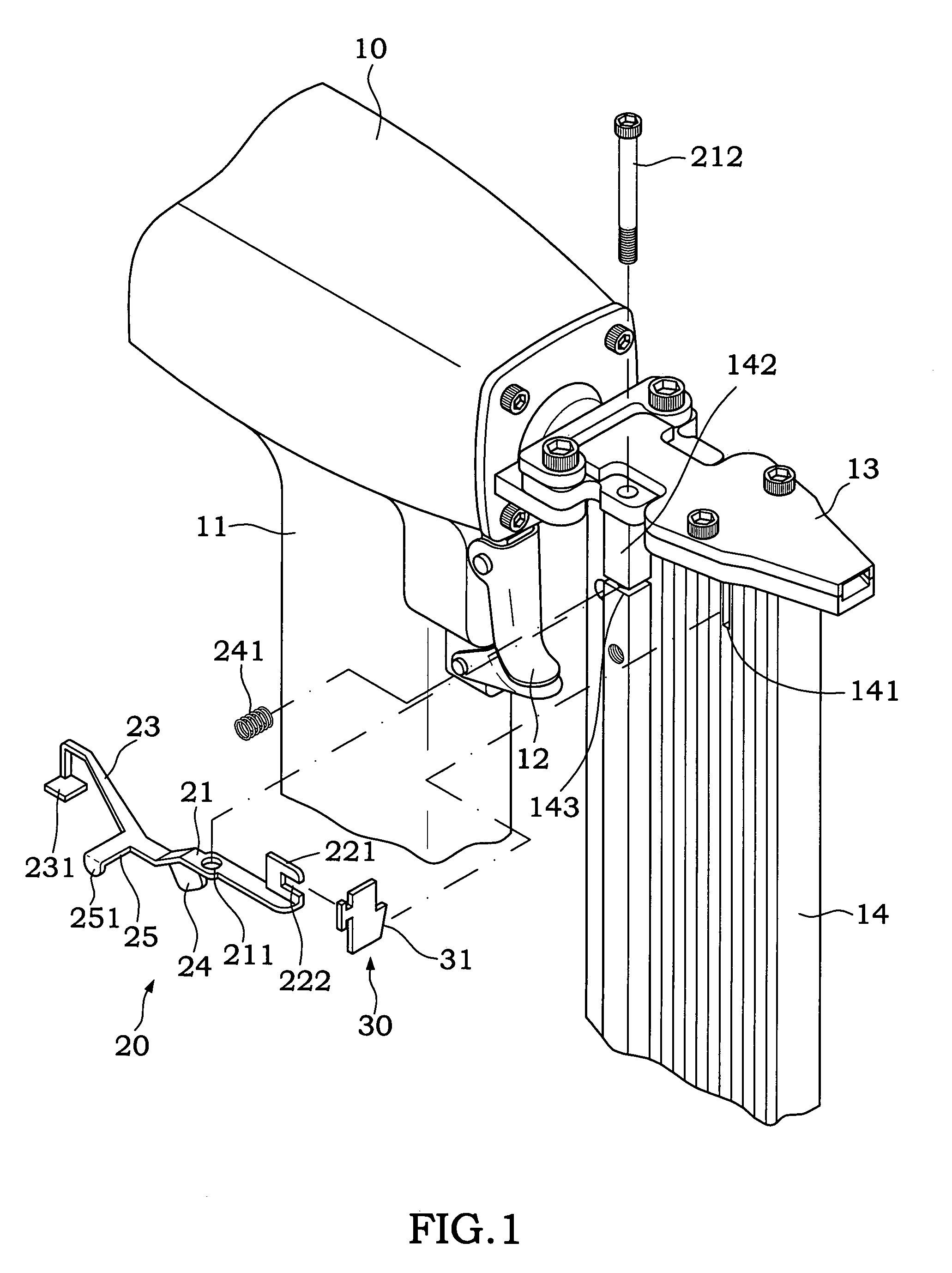
[0004]The primary objective of the present invention is to provide a safety catch mechanism for preventing users from shooting without nails in the magazine. By means of a blocking plate and a rotary rod, if there is no nail in the magazine, the blocking plate will block the rear of the trigger and prevent the trigger from being cocked. If the magazine is loaded with nails, then the latch can be pushed to drive the push arm to rotate outward, such that the blocking plate is separated from the rear of the trigger, and thus allowing users to cock the trigger. Therefore, the present invention can effectively prevent user from shooting a nail gun without nails in the magazine, and thus preventing the structure of the firing device and firing pin from being damaged or the life of use shortened due to the firing without having nails in the magazine.

Problems solved by technology

However, when users use such prior-art nail gun, the nails are shot continuously without knowing the current quantity of nails in the magazine.
As to the structure of the nail gun, shooting by a firing pin or other firing device without nails in the magazine may have adverse effects on the life of the nail gun or even cause damages to the nail gun.

Method used


Image

  • Safety catch mechanism of nail guns
  • Safety catch mechanism of nail guns
  • Safety catch mechanism of nail guns

Examples


Embodiment Construction

[0015]To make it easier for our examiner to understand the objective of the invention, its structure, innovative features, and performance, we use a preferred embodiment together with the attached drawings for the detailed description of the invention.

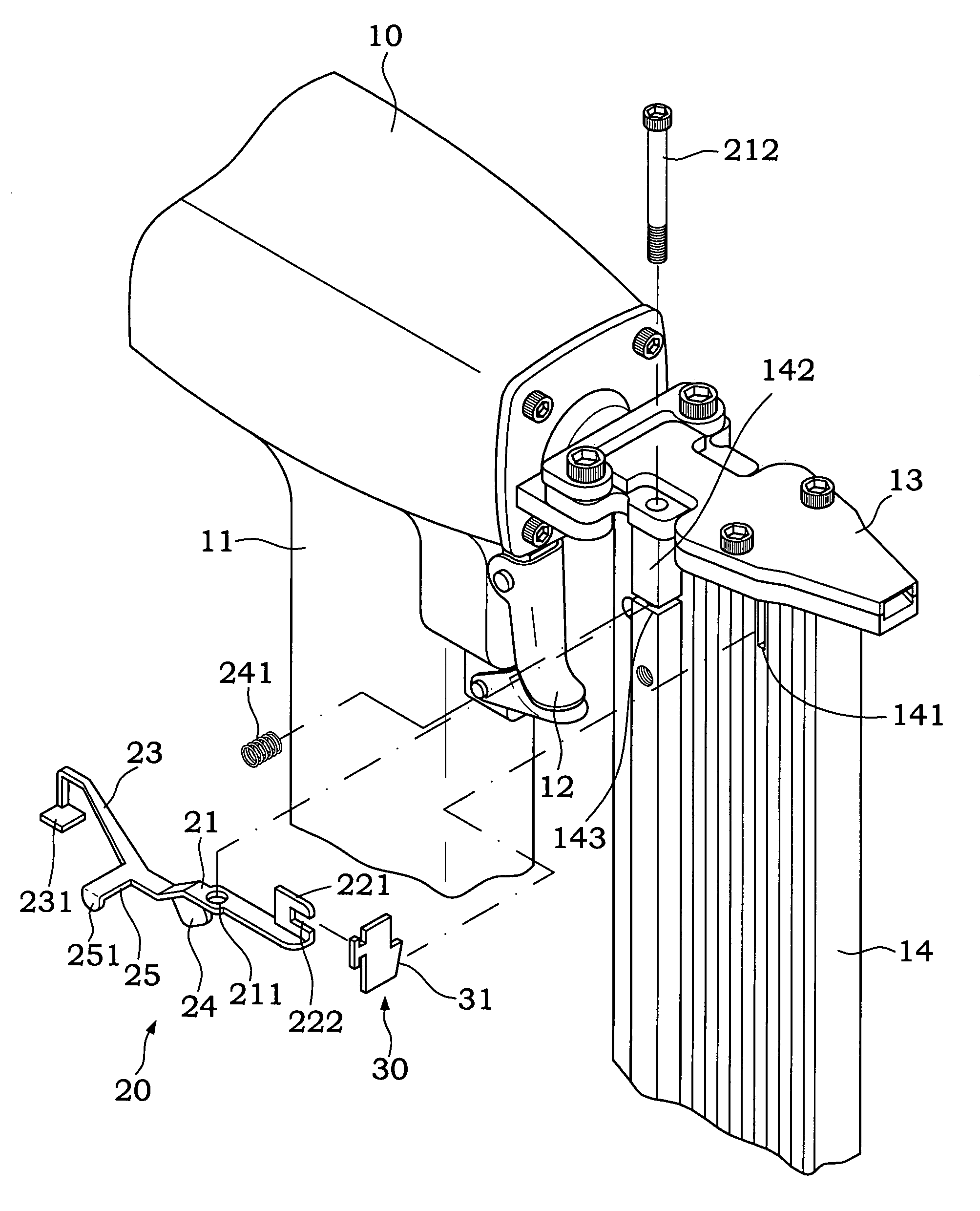
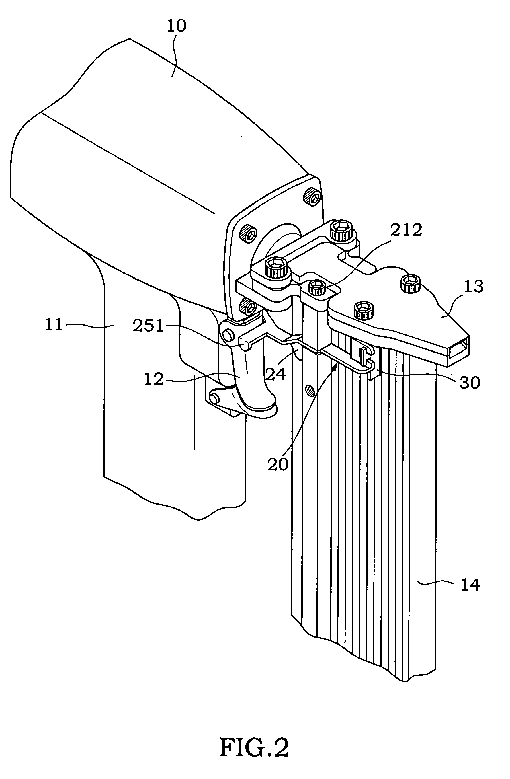
[0016]Please refer to FIGS. 1 to 3 for a safety catch mechanism of the present invention, which comprises:[0017]a main body 10, having a trigger 12 disposed on a handle 11, and a muzzle 13 disposed at the front end of the main body 10, a magazine 14 disposed under the muzzle 13 and interconnected with the muzzle 13, and a nail feeder 15 disposed in the magazine 14 for continuously pushing the nails stored in the magazine 14 out towards the muzzle 13; wherein a through hole 141 is disposed on an upper wall of the magazine 14; an axle section 142 is protruded from a side of the magazine 14; and a transversal groove 143 is transversally disposed on the axle section 142;[0018]a rotary rod 20, disposed on an axial section 21, and the axial ...


PUM

PropertyMeasurementUnit
Forceaaaaaaaaaa
Safety-related propertiesaaaaaaaaaa

Abstract

A safety catch mechanism for nail guns comprises a through hole at the upper end of a magazine of the nail gun, an axle section protruded from one side of the magazine and pivotally coupled with a rotary rod, a blocking arm extended from the rear end of the rotary rod, a blocking plate bent from the rear end of the blocking arm for being extended and blocking the rear of the trigger; wherein a push arm is extended from the front end of the rotary rod; a limit bracket is movably embedded at the end of the push arm; a latch is defined on the limit plate to be protruded from an inner wall of the magazine; by means of the foregoing structure, if the magazine is loaded with nails, the latch can be pushed outward to drive the rotary rod to rotate, so that the blocking plate is separated from the rear of the trigger and allows users to cock the trigger.

Description

FIELD OF THE INVENTION[0001]The present invention relates to a nail gun assembly, more particularly to a nail gun assembly with a safety catch mechanism for preventing users from shooting the nail gun without nails.BACKGROUND OF THE INVENTION[0002]In general, a prior-art nail gun usually comprises a muzzle disposed at the front end of a nailing device in the main body of the nail gun, a magazine interconnectably disposed at the bottom of the muzzle for accommodating and storing nails. Further, a trigger is disposed on the handle of the main body of the nail gun for controlling the high-pressure airflow inside the nail gun and a firing pin of the nail gun for the shooting. By the shooting force of the firing pin, the nail in the muzzle can be shot into a work piece.[0003]However, when users use such prior-art nail gun, the nails are shot continuously without knowing the current quantity of nails in the magazine. Therefore, after the nails in the magazine are exhausted, users may cont...

Claims


Application Information

Patent Timeline
IPC IPC(8): B25C1/00
CPCB25C1/008B25C1/005
Inventor WANG, GUAN-HE
Owner NAILERMATE ENTERPRISE
Learn More