
Method and system for efficiently traversing an area with a work vehicle

a work vehicle and efficient technology, applied in the direction of distance measurement, thinning machines, instruments, etc., can solve the problems of waste of fuel, excessive or inconsistent row overlap between adjacent rows, and the operator may not be able to achieve precise row alignment of adjacent rows

Inactive Publication Date: 2005-06-14
DEERE & CO
View PDF16 Cites 121 Cited by
  • Summary
  • Abstract
  • Description
  • Claims
  • Application Information

AI Technical Summary

Benefits of technology

The invention is about a method for creating a border in a work area and aligning rows of vehicles in a way that allows for a smooth transition between them. The method involves defining a designated area and a designated axis, and then aligning rows of vehicles in a way that keeps them parallel to the designated axis. The first row is defined as the starting row, and the vehicle moves in a straight line along the designated axis until it reaches the next row. The next row is then turned at a point where it is perpendicular to the designated axis, and the vehicle moves in a straight line until it reaches the next row. This process creates a smooth transition between rows and ensures that the vehicles are always aligned properly.

Problems solved by technology

An operator of a work vehicle may be exposed to chemicals, fertilizers, herbicides, insecticides, dust, allergens, exhaust fumes, environmental conditions, slopes, low-hanging branches, and other hazards or conditions that might be harmful or irritating to the operator.
Further, an operator may not be able to achieve precise row alignment of adjacent rows because of the limited perspective of a human operator from a work vehicle or other factors.
The misalignment of rows may lead to excessive or inconsistent row overlap between adjacent rows.
In turn, excessive or inconsistent overlap may lead to one or more of the following: wasted fuel, wasted disbursed materials, unharvested crop, and poor aesthetic appearance of the mowed area or processed vegetation.

Method used


Image

  • Method and system for efficiently traversing an area with a work vehicle
  • Method and system for efficiently traversing an area with a work vehicle
  • Method and system for efficiently traversing an area with a work vehicle

Examples


Embodiment Construction

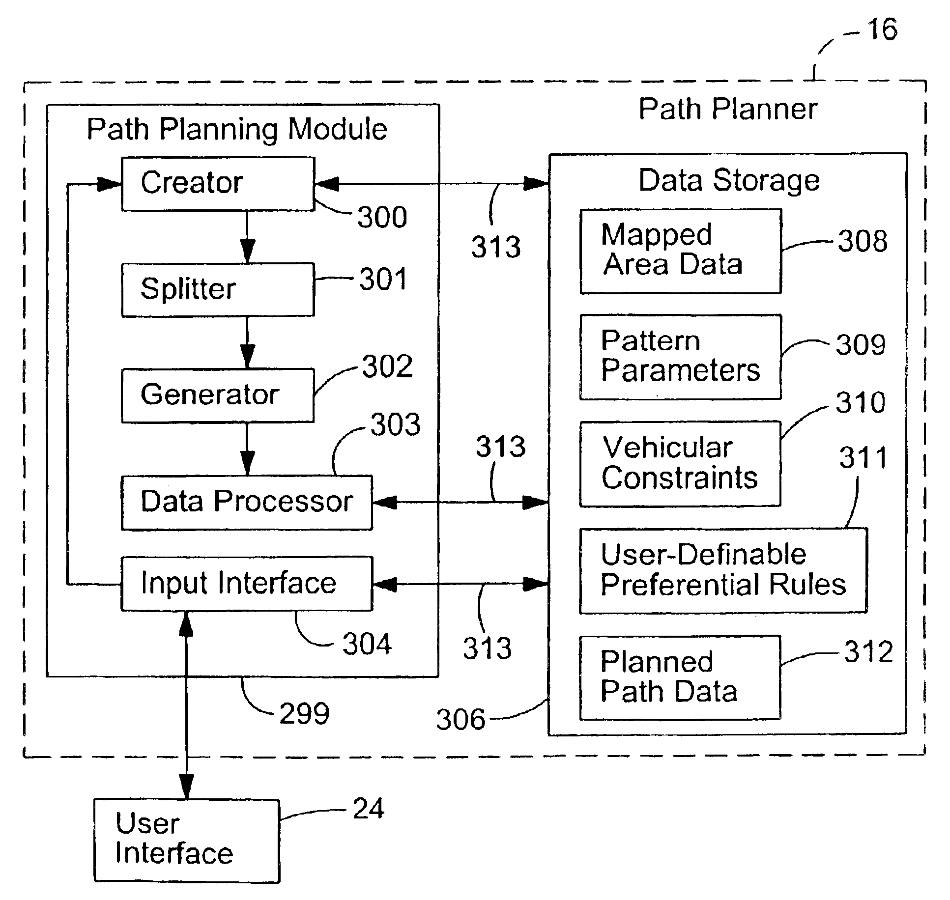
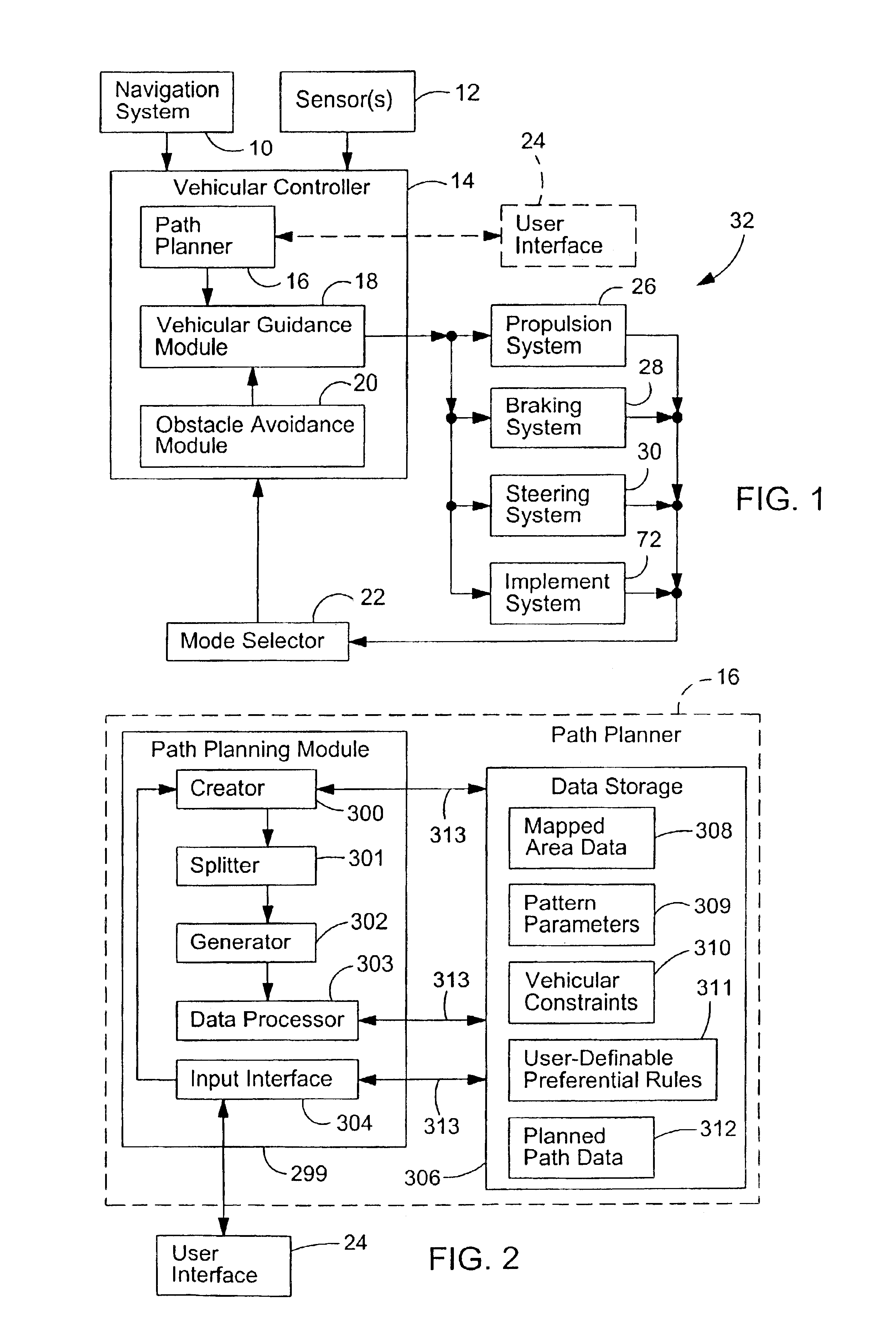
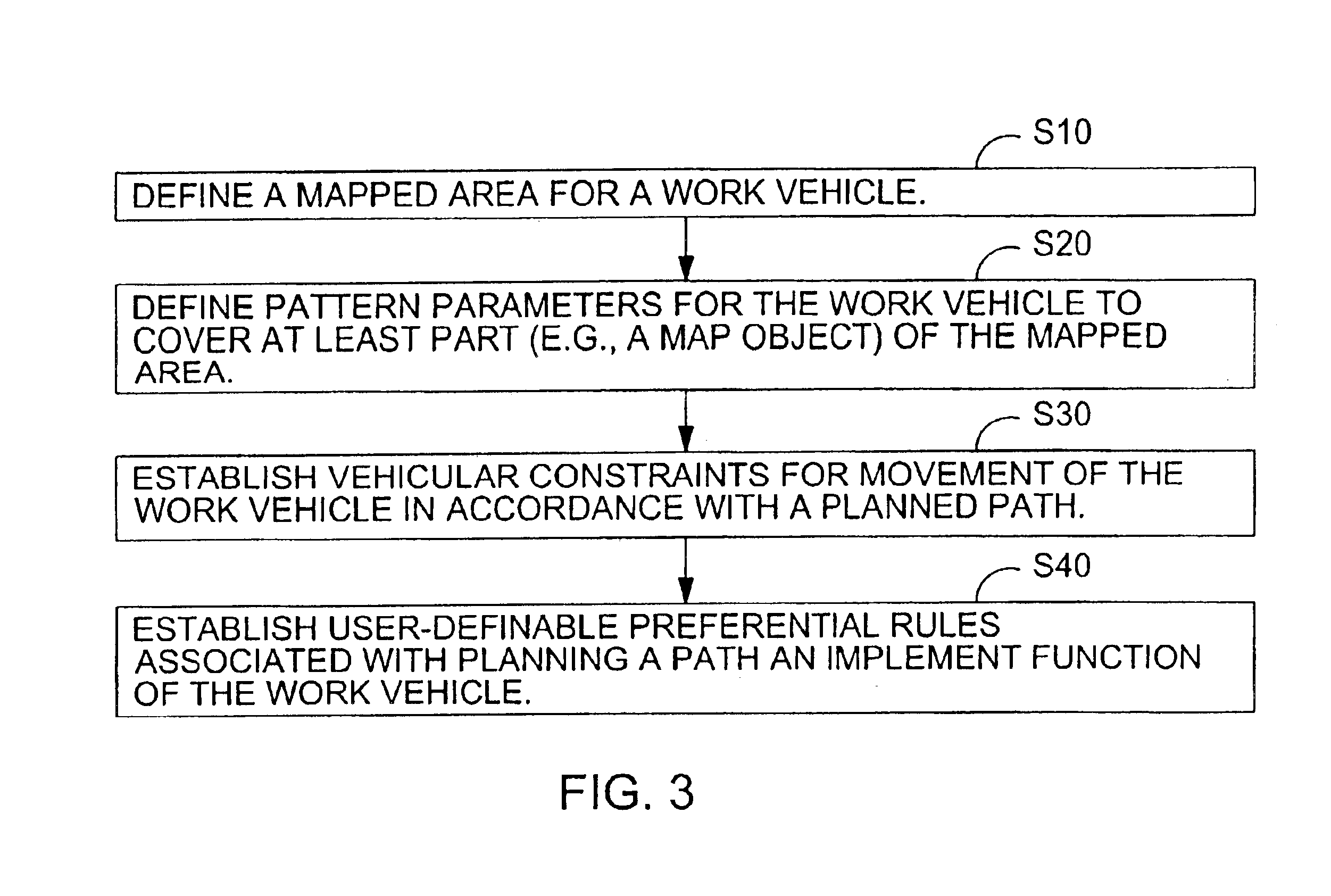
[0017]A mapped area means a work area with boundaries that are mapped or otherwise defined. A designated area may refer to any portion of the work area or the entire work area. The designated area may mean a map object. A map object refers to a desired portion of the mapped area to be mowed, sprayed, harvested, treated, covered, processed or otherwise traversed to accomplish a task. The boundaries of the mapped area and the boundaries map object may be defined to be coextensive with each other, partially contiguous with each other or noncontiguous with each other.

[0018]In accordance with one embodiment of the invention, FIG. 1 shows a block diagram of a system for controlling a vehicle, such as a mower, a stadium mower or another work vehicle. A vehicular controller 14 is coupled to a navigation system 10 and one or more sensors 12. The vehicular controller 14 is associated with a mode selector 22 for selection of one or more modes of operation of the vehicle. The vehicular controll...


PUM


Abstract

A border of a designated area is defined within a work area. A designated axis is determined for the designated area. A series of generally parallel rows are aligned consistent with a travel axis having a known alignment with respect to the designated axis. One of the generally parallel rows is aligned as a starting row. The vehicle is pointed in a starting direction along or generally parallel to the travel axis. The vehicle engages in a turn path segment after an end of the starting row to move the vehicle at least somewhat perpendicular to the travel axis between the starting row and a next row. A turn path segment has a turn radius greater than or equal to a minimum turning radius of the vehicle, where the starting row and the next row are spatially separated by a multiple of effective vehicular implement widths less an overlap allowance. The turn path segment is defined so as to skip one or more intervening parallel rows between the starting row and the next row.

Description

[0001]This application is a continuation-in-part of U.S. application Ser. No. 10 / 403,681 entitled, A PATH PLANNER AND A METHOD FOR PLANNING A PATH OF A WORK VEHICLE, filed Mar. 31, 2003 (pending), and this application is entitled to the benefit of the foregoing prior application under 35 U.S.C. 120.FILED OF THE INVENTION[0002]This relates to a method and system for efficiently traversing an area with a work vehicle.BACKGROUND OF THE INVENTION[0003]An operator of a work vehicle may be exposed to chemicals, fertilizers, herbicides, insecticides, dust, allergens, exhaust fumes, environmental conditions, slopes, low-hanging branches, and other hazards or conditions that might be harmful or irritating to the operator. Further, an operator may not be able to achieve precise row alignment of adjacent rows because of the limited perspective of a human operator from a work vehicle or other factors. The misalignment of rows may lead to excessive or inconsistent row overlap between adjacent ro...

Claims


Application Information

Patent Timeline
Patent Type & Authority Patents(United States)
IPC IPC(8): A01B69/04
CPCA01B69/008G05D1/0219G05D1/0217
Inventor GRAY, SARAH ANNHANSEN, SHANE LYNNFLANN, NICHOLAS SIMON
Owner DEERE & CO
Learn More