
Electronic tunable filters with dielectric varactors

a dielectric varactor and tunable filter technology, applied in the field of electronic filters, can solve the problems of large volume of microwave filters in communications circuits, large tunable filter size, and heavy weigh

Inactive Publication Date: 2005-06-07
NXP USA INC
View PDF29 Cites 19 Cited by
  • Summary
  • Abstract
  • Description
  • Claims
  • Application Information

AI Technical Summary

Problems solved by technology

However, microwave filters occupy a large volume in communications circuits, especially in multi-band applications.
Both mechanically and magnetically tunable filters are relatively large in size and heavy in weight.

Method used


Image

  • Electronic tunable filters with dielectric varactors
  • Electronic tunable filters with dielectric varactors
  • Electronic tunable filters with dielectric varactors

Examples


Embodiment Construction

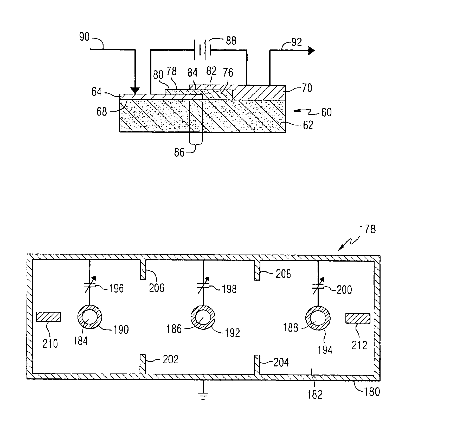
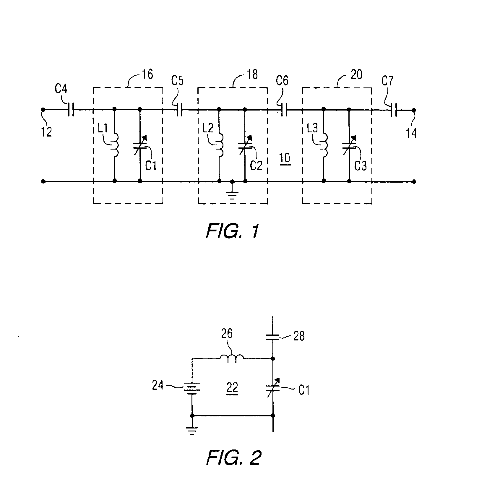
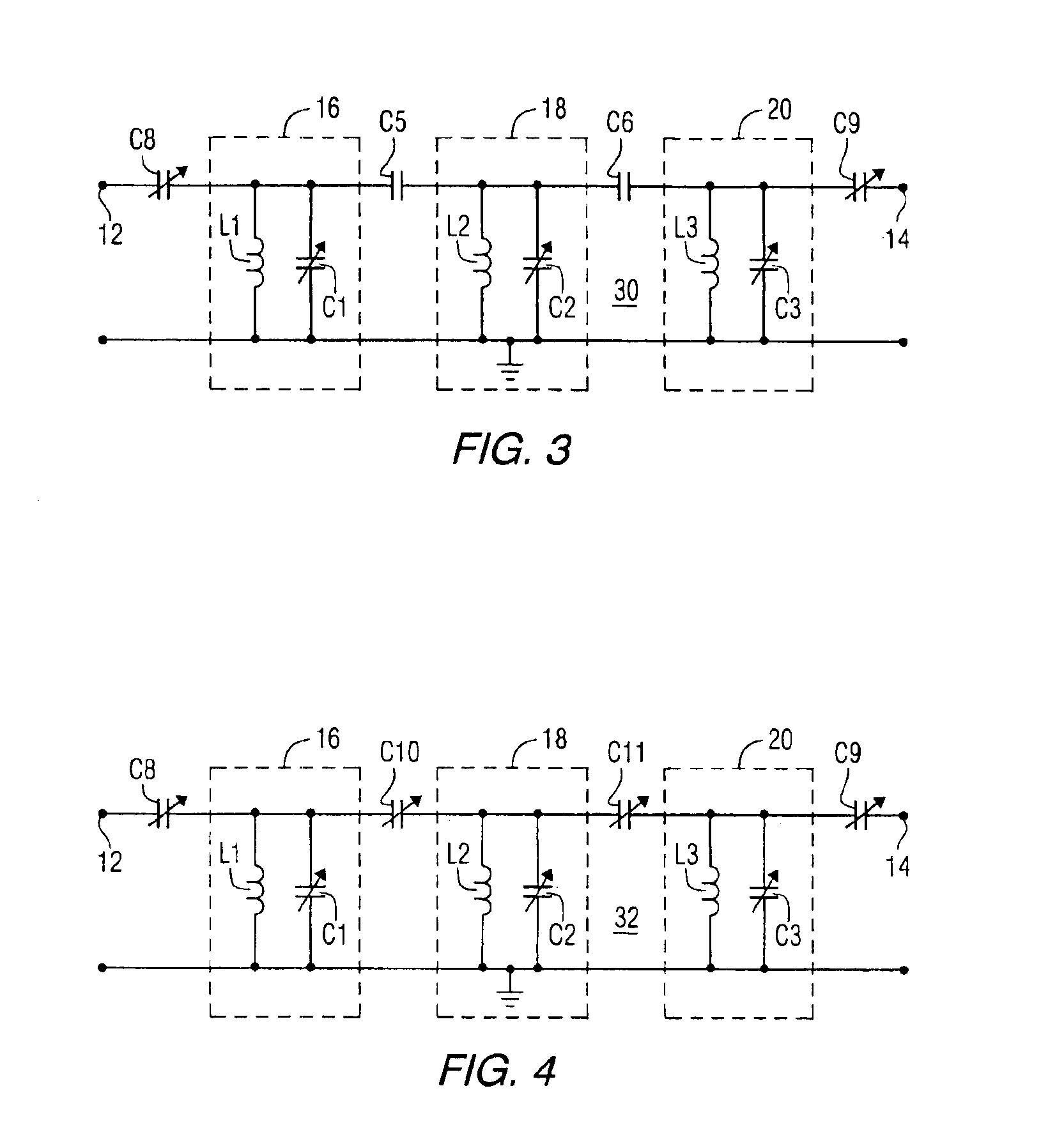
[0035]Referring to the drawings, FIG. 1 is a schematic diagram of a three pole lumped element LC tunable filter 10 constructed in accordance with one embodiment of the invention. The filter includes an input 12 and an output 14. A plurality of resonant circuits 16, 18 and 20 are electrically coupled to the input and the output. Resonant circuit 16 includes inductor L1 and capacitor C1. Resonant circuit 18 includes inductor L2 and capacitor C2. Resonant circuit 20 includes inductor L3 and capacitor C3. Capacitor C4 couples resonant circuit 16 to the input 12. Capacitor C5 couples resonant circuit 16 to resonant circuit 18. Capacitor C6 couples resonant circuit 18 to resonant circuit 20. Capacitor C7 couples resonant circuit 20 to the output 14. Capacitors C1, C2 and C3 are tunable dielectric varactors. C4 and C7 are port coupling capacitors used to provide a specific port impedance, typically 50 ohms or 75 ohms. More or fewer resonators can be used in the filter to obtain specific fi...


PUM


Abstract

A radio frequency electronic filter includes an input, an output, and first and second resonators coupled to the input and the output, with the first resonator including a first voltage tunable dielectric varactor and the second resonator including a second voltage tunable dielectric varactor. The resonators can include a lumped element resonator, a ceramic resonator, or a microstrip resonator. Additional voltage tunable dielectric varactors can be connected between the input and the first resonator and between the second resonator and the output. Voltage tunable dielectric varactors can also be connected between the first and second resonators.

Description

CROSS-REFERENCE TO RELATED APPLICATION[0001]This application is a divisional of patent Ser. No. 09 / 734,969, entitled, “ELECTRONIC TUNABLE FILTERS WITH DIELECTRIC VARACTORS”, filed Dec. 12, 2000, by Yongfei Zhu et al., that issued as U.S. Pat. No. 6,686,817 on Feb. 3, 2004.BACKGROUND OF INVENTION[0002]The present invention generally relates to electronic filters and, more particularly, to such filters that include tunable dielectric capacitors (dielectric varactors).[0003]One of most dramatic developing areas in communications over the past decade has been mobile and portable communications. This has led to continual reductions in the size of the terminal equipment such as the handset phone. Size reduction of the electronic circuits is progressing with the development of recent semiconductor technologies. However, microwave filters occupy a large volume in communications circuits, especially in multi-band applications. Multi-band applications typically use fixed filters to cover diff...

Claims


Application Information

Patent Timeline
Patent Type & Authority Patents(United States)
IPC IPC(8): H01P1/203H01P1/20H01P1/205
CPCH01P1/20336H01P1/2056H01P1/20381
Inventor ZHU, YONGFEISENGUPTA, LOUISE C.
Owner NXP USA INC
Learn More