
Method and apparatus for magnetically controlling endoscopes in body lumens and cavities

a technology of endoscopes and magnetic control, which is applied in the field of magnetic control of endoscopes in body lumens and cavities, can solve the problems of increasing navigation difficulty, reducing control over the movement of the endoscope tip, and using endoscopes, and achieves the effect of quick and intuitive control

Inactive Publication Date: 2005-06-07
STEREOTAXIS
View PDF7 Cites 339 Cited by
  • Summary
  • Abstract
  • Description
  • Claims
  • Application Information

AI Technical Summary

Benefits of technology

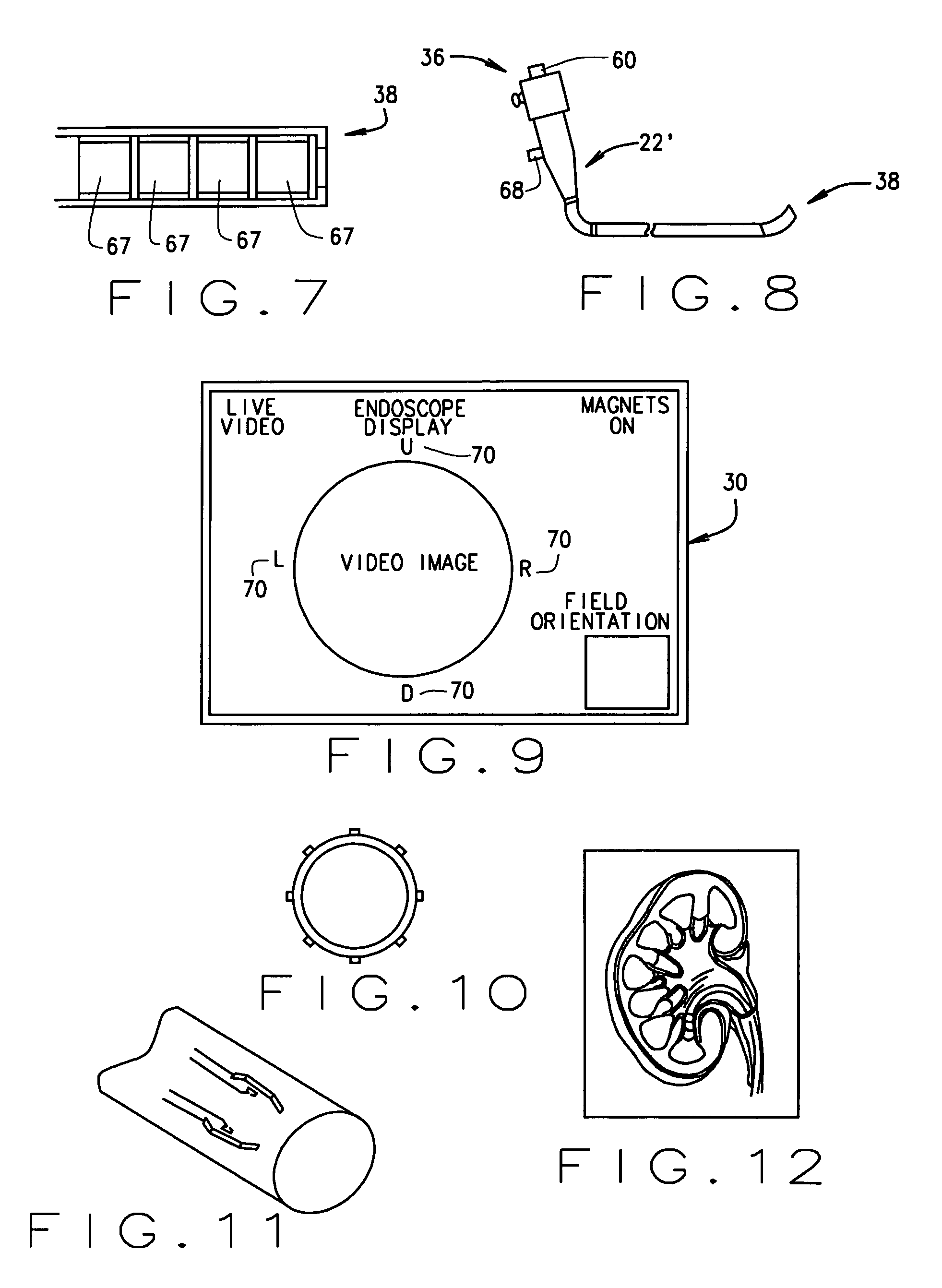
[0008]The magnetically navigable endoscope system of the present invention allows a health care professional to quickly and intuitively navigate the endoscopes through body lumens and cavities. In the preferred embodiment, the system interface allows the health care professional to move the endoscope through the body without having to get involved in directly controlling the magnetic field direction and strength. This is achieved by allowing the physician to directly visualize the body lumen or cavity in which the endoscope is located, and navigate based on this viewed image.

Problems solved by technology

One of the greatest difficulties in using endoscopes is navigating the distal end of the endoscope within the body to the procedure site.
Another problem with wire-controlled endoscopes is that the control over the movement of the tip of the endoscope diminishes with each successive bend in the endoscope, so as the endoscope is navigated through a particularly tortuous path through the body, navigation becomes increasingly difficult.
However, it can be difficult for a medical professional to quickly and easily control the magnetic field in order to effectively magnetically navigate an endoscope.

Method used


Image

  • Method and apparatus for magnetically controlling endoscopes in body lumens and cavities
  • Method and apparatus for magnetically controlling endoscopes in body lumens and cavities
  • Method and apparatus for magnetically controlling endoscopes in body lumens and cavities

Examples


Embodiment Construction

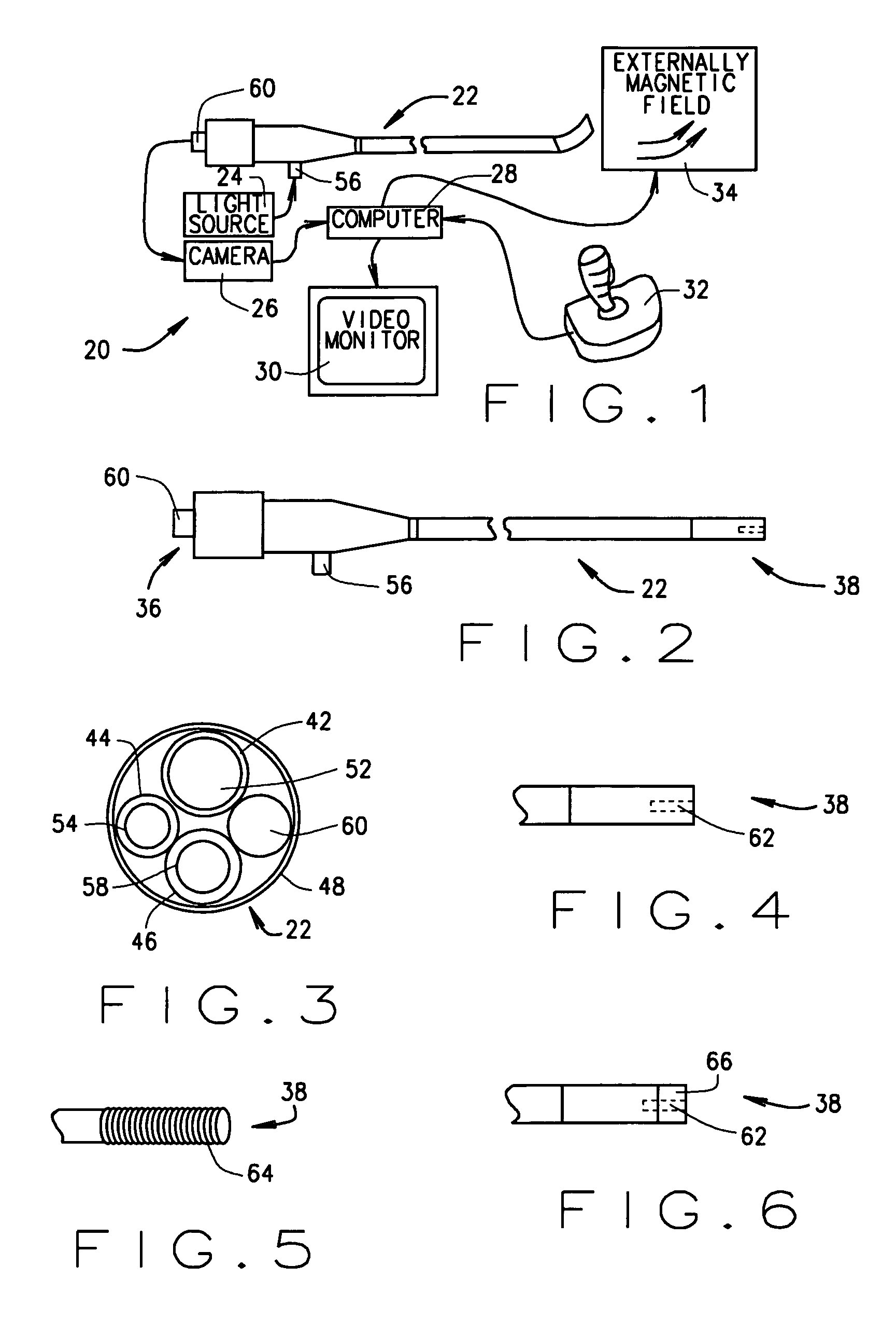
[0023]A system for navigating endoscopes through body lumens and cavities is indicated generally as 20 in FIG. 1. The system 20 comprises an endoscope 22, a light source 24 connected to the endoscope to provide light to illuminate the body lumen or cavity surrounding the distal end of the endoscope, an imaging device 26, for example a camera, for capturing images of the body lumen or cavity surrounding the distal end of the endoscope and a computer 28 for processing the image captured by the imaging device 26 and displaying the image on a display 30. Of course instead of a camera for capturing optical images, the imaging device could be an ultrasonic imaging device or an infrared imaging device, or some other suitable imaging device. The computer 28 is also connected to a controller, such as a controller 32, for receiving input for controlling endoscope 22, and processing the input to create an output control signal to the magnetic field generating device 34 to control the magnetic ...


PUM


Abstract

A magnetically navigable endoscope system includes an endoscope having a proximal end and a distal end, the distal end having a magnetic body; a component which transmits an image, associated with the distal end; a display component for displaying the image; a magnetic field generating apparatus for generating a magnetic field to orient the magnetic body and thus the distal end of the endoscope; and a controller coordinated with the display for controlling the magnetic field generating apparatus to selectively change the magnetic field to change the orientation of the magnetic body and thus the distal end of the endoscope.

Description

FIELD OF THE INVENTION[0001]This invention relates to magnetically controlling endoscopes, and in particular to a method and apparatus for magnetically controlling endoscopes in body lumens and cavities.BACKGROUND OF THE INVENTION[0002]Endoscopes, which allow viewing of the interior of body lumens and cavities, are increasingly used in conducting medical procedures. One of the greatest difficulties in using endoscopes is navigating the distal end of the endoscope within the body to the procedure site. Standard endoscopes are steered using articulation wires secured to the distal end and which extend to the proximal end, where they can be operated by mechanisms incorporated in the proximal end of the endoscope. The articulation wires pull the distal end of the endoscope, causing it to articulate in the desired direction. Some endoscopes have a single plane of articulation, and navigation is affected by a combination of articulation and rotation of the endoscope. Other endoscopes have...

Claims


Application Information

Patent Timeline
Patent Type & Authority Patents(United States)
IPC IPC(8): A61B1/005A61B1/01
CPCA61B1/00158A61B1/01A61B1/0005A61B1/00039A61B5/6885A61B1/0051A61B1/00071A61B1/00042
Inventor GARIBALDI, JEFFREY M.BLUME, WALTER M.EPPLIN, GERARD H.
Owner STEREOTAXIS
Learn More