
Vehicle rear gate opening and closing apparatus

Inactive Publication Date: 2005-06-07
FUJI JUKOGYO KK
View PDF19 Cites 28 Cited by
  • Summary
  • Abstract
  • Description
  • Claims
  • Application Information

AI Technical Summary

Benefits of technology

[0012]It is a first object of the present invention to provide a compact rear gate opening and closing apparatus capable of automatically opening and closing a rear gate without hindering an interior space of the passenger compartment. It is a second object of the present invention to provide a rear gate opening and closing apparatus capable of opening and closing the rear gate not only automatically but also by hand. It is a third object of the present invention to provide a rear gate opening and closing apparatus capable of properly regulating the opening and closing speed.

Problems solved by technology

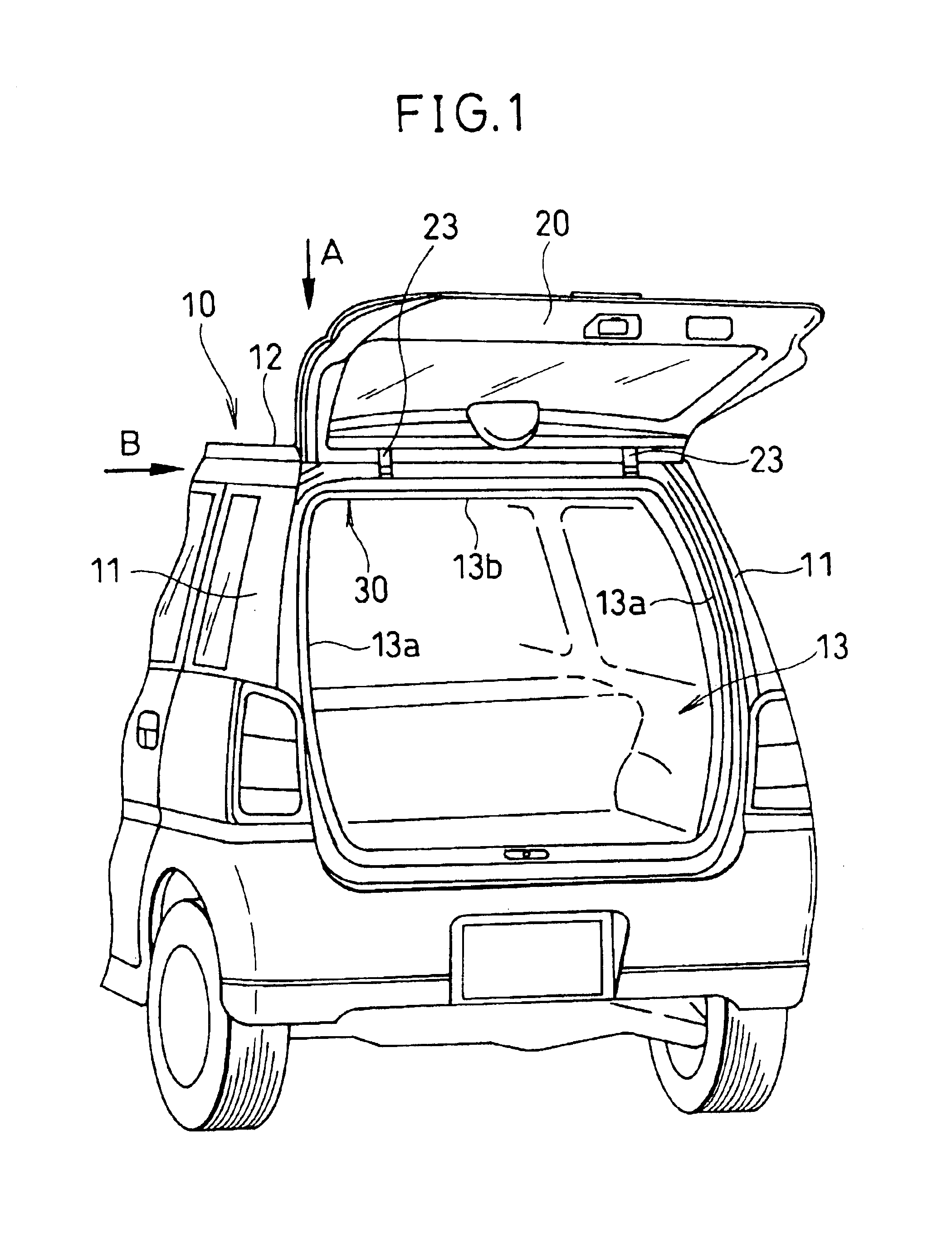
Further, since the gas stay 105 is exposed to the compartment, there is a problem that the interior space is limited as much and also there is an aethetic problem.
That is, the freedom of the rear design of the vehicle is restricted.
The opening and closing effort of the rear gate is generally troublesome to the operator and particularly, when it rains heavily and his or her hands are full with baggage, it is desirable that an opening and closing apparatus for automatically opening and closing the rear gate can be operated by the operator while he or she stays in the passenger compartment.

Method used


Image

  • Vehicle rear gate opening and closing apparatus
  • Vehicle rear gate opening and closing apparatus
  • Vehicle rear gate opening and closing apparatus

Examples


first embodiment

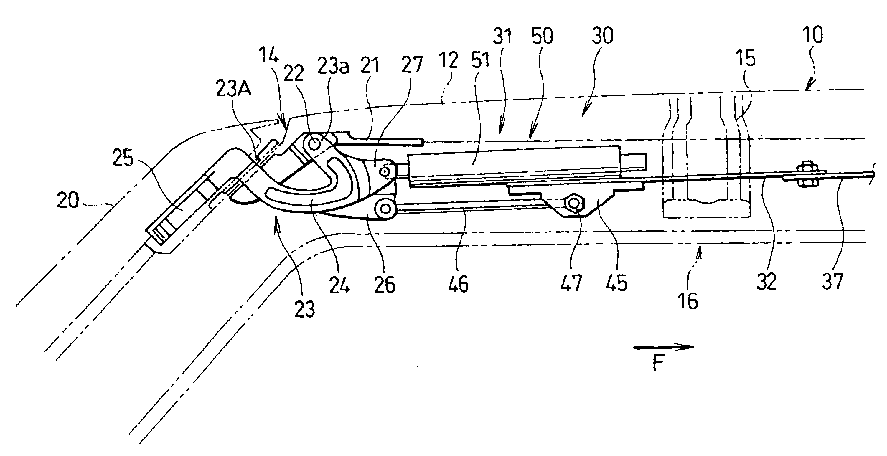
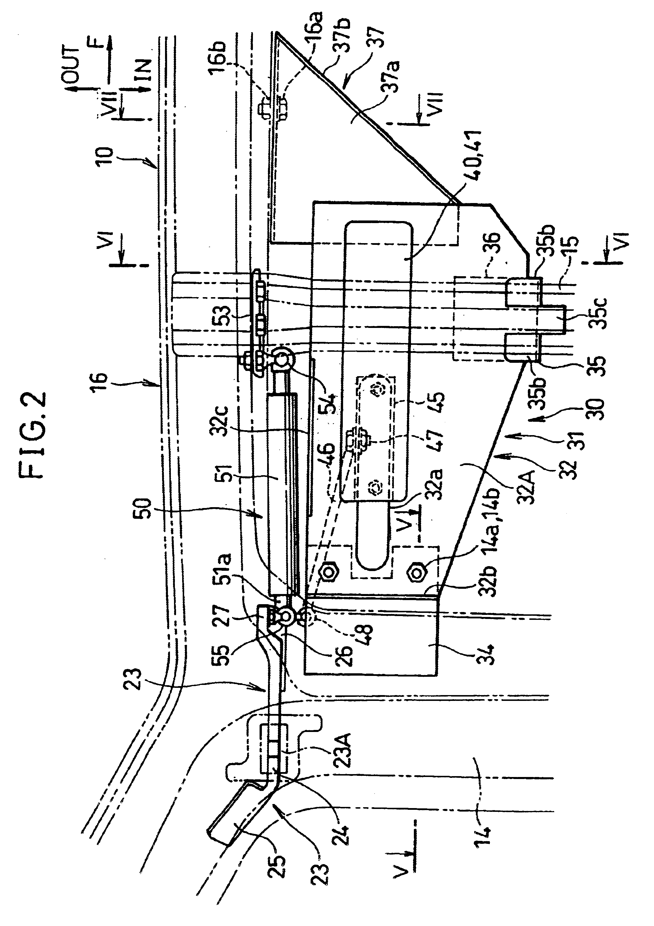
[0031]FIG. 2 shows a drive unit of a rear gate opening and closing mechanism according to the present invention and FIG. 3 shows a drive unit of the rear gate opening and closing mechanism. In FIGS. 2 and 3, the vehicle body 10 and the rear gate 20 are shown by two-dots chain lines.

[0032]The hinge arm 23 is rotatably supported at the end boss 23a thereof by a pivot 22 secured to an hinge base 21 which is attached to the neighborhood of the rear end of a roof 12. Describing the state where the rear gate 20 is closed, the hinge arm 23 extending downwardly and forwardly from the end boss 23a, forms a bent section 24. The bent section 24 extends backwardly being bent in a circle around the pivot 22, penetrates through a hinge arm penetrating hole 23A provided in a rear rail 14 and projects the rear end thereof outside. The rear end has a rear gate mounting bracket 25 for mounting the rear gate 20 and the front end of the bent section 24 has a connecting rod connection section 26 and a g...

second embodiment

[0056]FIG. 8 shows a rear gate opening and closing mechanism according to a The power unit module 40 includes the motor 41 described before, a clutch 42 and an encoder 43. Further, an electronic control unit (hereinafter, referred to as ECU) 60 is disposed in the vehicle and makes an automatic opening and closing control of the rear gate 20.

[0057]The clutch 42 connects the motor 41 with the slider 45 when it is energized and the connection is released when it is deenergized. When an operator wants to open or close the rear gate 20 manually, a handle switch 62 which will be described hereinafter is operated and the ECU 60 detects this to deenergize the clutch 42. When the clutch is deenergized, the motor 41 is disengaged with the slider 45 and the rear gate 20 can be operated to open or close manually. On the other hand, when the operator wants to open or close the rear gate 20 automatically, the clutch 42 is energized to engage the motor 41 with the slider 45. As a result, the rear...


PUM


Abstract

A rear gate opening and closing apparatus includes a gas stay for biasing a rear gate in an opening direction, a motor for actuating to open or close the rear gate, a clutch for connecting or disconnecting the motor with the rear gate, an encoder for detecting the position of the rear gate, an operating switch for operating an opening and closing motion of the rear gate, and a control means for controlling the motor and clutch to automatically open and close the rear gate. The opening and closing speed of the rear gate is controlled based on a detection signal of the encoder.

Description

BACKGROUND OF THE INVENTION[0001]1. Field of the Invention[0002]The present invention relates to a vehicular rear gate opening and closing apparatus whose upper end is pivotally connected with a vehicle body so as to swing up and down and more particularly to a rear gate capable of opening and closing in two ways by an actuator or by hand.[0003]2. Discussion of Prior Art[0004]As shown in FIG. 11, generally a rear gate 102 disposed in the rear of a vehicle is a lid swinging up and down for opening and closing an opening 101. The rear gate 102 is at the upper end thereof secured to a hinge arm 103 rotatably supported by an upper edge of the opening 101 of a vehicle body 100.[0005]A gas stay 105 is connected between a side edge of the rear gate 102 and a side edge 104a of the opening 101 formed along a rear pillar 104. The gas stay 105 has a piston rod 105a biased in an axial (longitudinal) direction by sealed gas pressure. When the rear gate 102 opens or closes, the gas stay 105 expan...

Claims


Application Information

Patent Timeline
IPC IPC(8): B60J5/10E05F15/12E05F1/10E05F1/00
CPCE05F15/63E05F1/1091E05Y2201/246E05Y2201/416E05Y2201/462E05Y2400/59E05Y2400/814E05Y2900/546E05F15/00E05Y2201/68E05Y2400/854E05Y2400/86E05Y2201/216E05Y2400/822E05Y2400/83
Inventor SAKAUE, HIROFUMIOKADA, KENJISUZUKI, NOBUZI
Owner FUJI JUKOGYO KK
Learn More