
Hardware assisted ATA command queuing

a command and hardware technology, applied in the field of computer systems, can solve the problems of occupying preventing the processor from performing other tasks, and consuming a significant amount of processor tim

Inactive Publication Date: 2005-05-31
INTEL CORP
View PDF5 Cites 120 Cited by
  • Summary
  • Abstract
  • Description
  • Claims
  • Application Information

AI Technical Summary

Benefits of technology

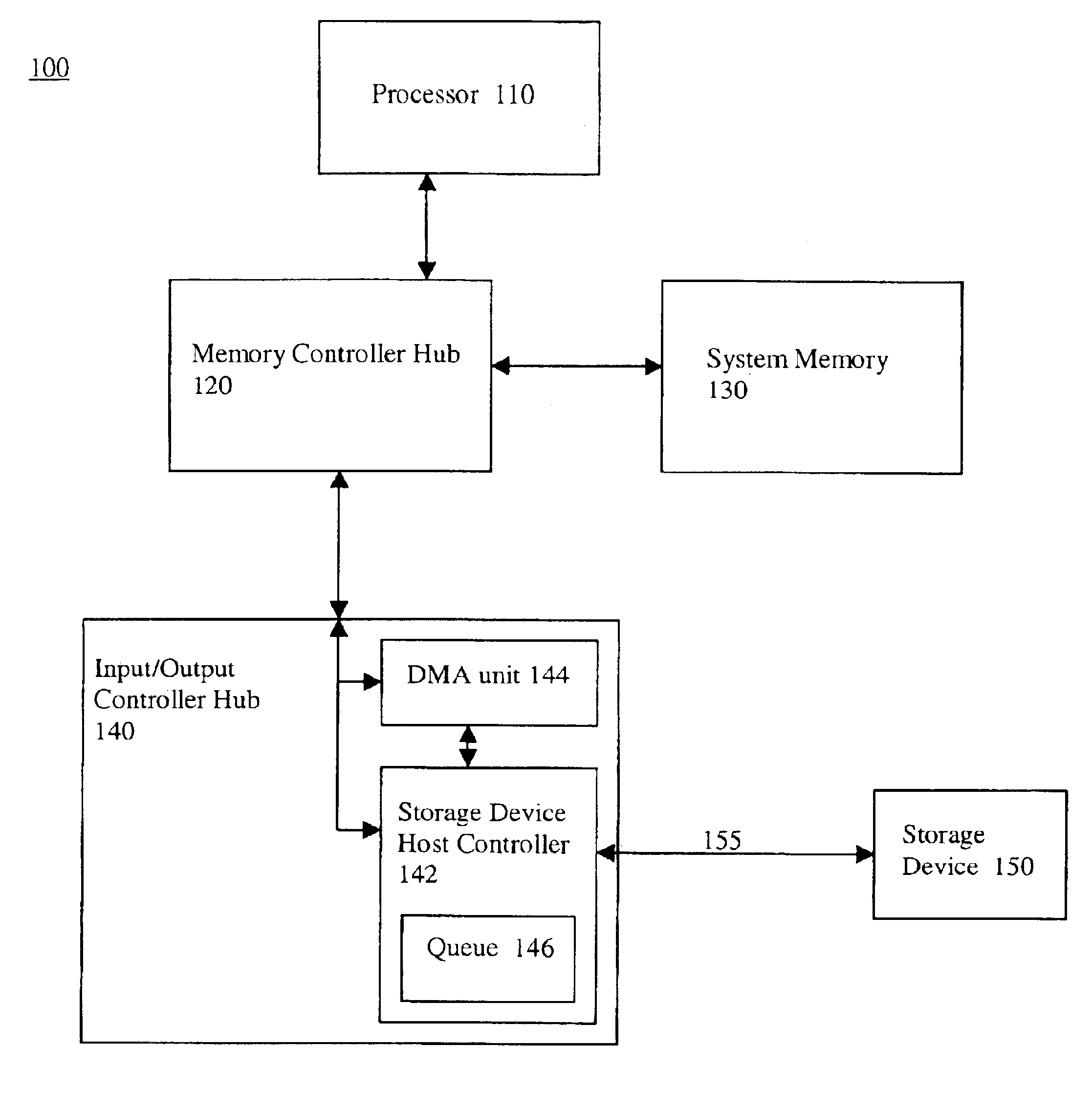
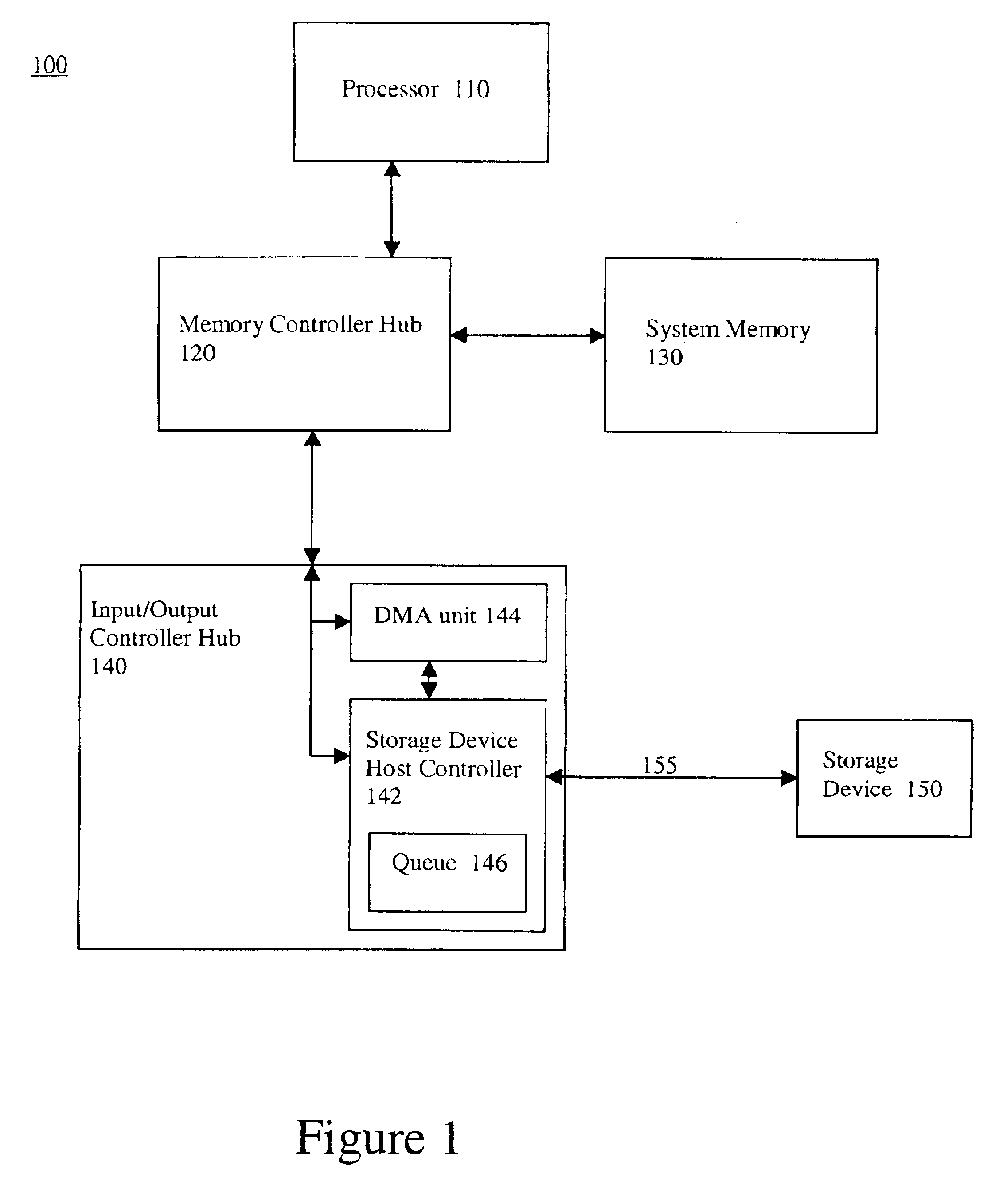
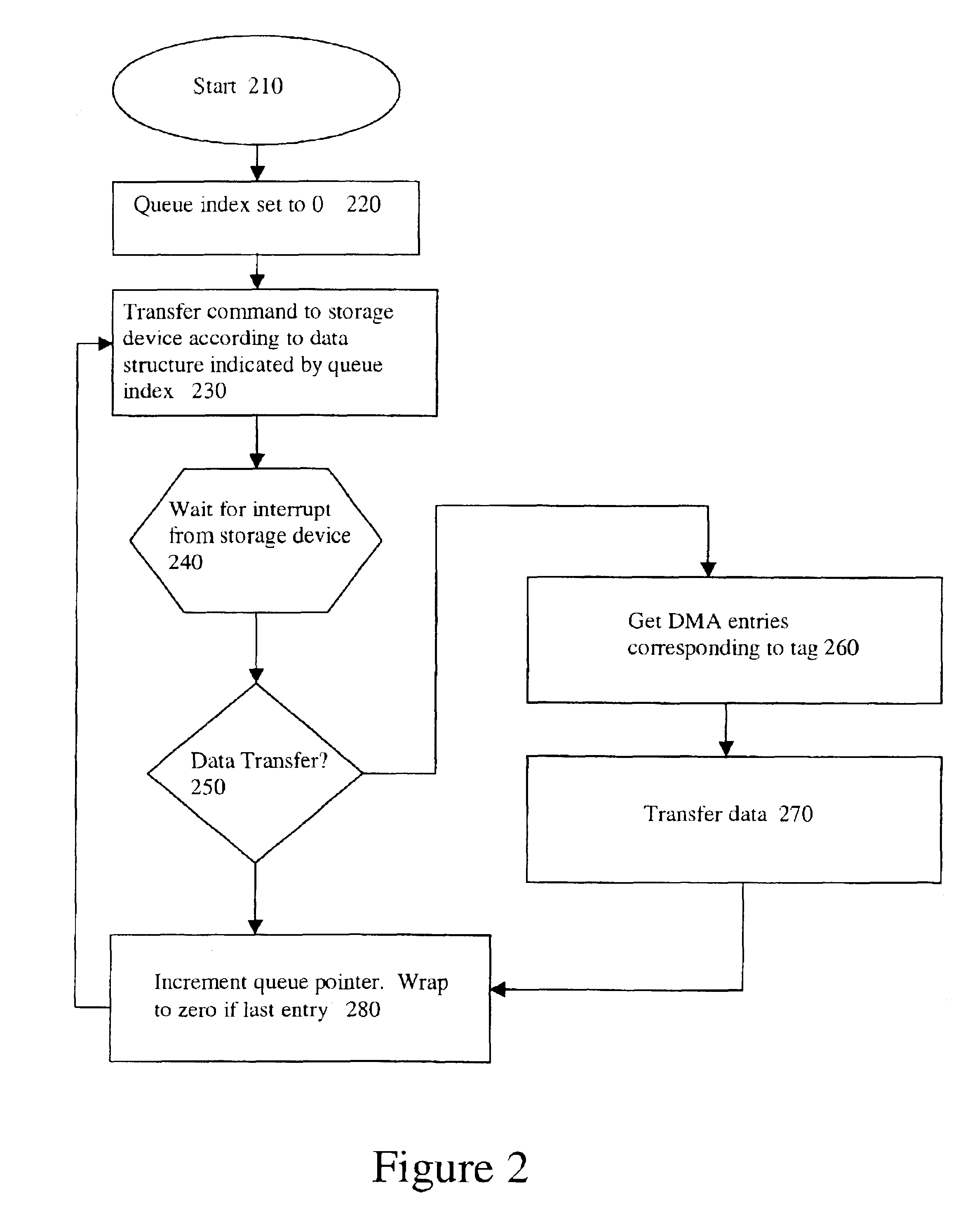
The present invention relates to a method for programming mass storage devices in computer systems more efficiently. The invention involves writing command information to cacheable system memory and then transferring the information to the storage device host controller through a single write cycle. The host controller then causes a DMA transfer to occur which reads the command information and stores it in a queue. The processor is only involved in setting up the command block in system memory and signaling the host controller that the command block is ready for reading. This frees up the processor to perform other tasks and improves overall system performance.

Problems solved by technology

This programming operation can take a significant amount of time and keep the processor from performing other tasks.
These tasks take up a significant amount of processor time and overall system performance is negatively affected.

Method used


Image

  • Hardware assisted ATA command queuing
  • Hardware assisted ATA command queuing
  • Hardware assisted ATA command queuing

Examples


Embodiment Construction

[0009]In general, one embodiment involves having a processor write disk drive command information for a number of data transactions to cacheable system memory. The processor then performs a single write transaction to a disk drive host controller. The disk drive host controller then causes a DMA transfer to occur which reads the command information located in system memory and stores the command information in a queue. Once the host controller has the command information, it programs the disk drive over a serial interconnect. The disk drive signals an interrupt after it processes the command information. The disk drive host controller does not forward the interrupt to the processor, but services the interrupt itself. The disk drive host controller reads from the disk drive to determine the disk drive status. The disk drive can signal that it is ready to execute the programmed command, or it can signal that it is not ready to perform the programmed command but is ready to receive add...


PUM


Abstract

One embodiment involves having a processor writing disk drive command information for a number of data transactions to cacheable system memory. The processor then performs a single write transaction to a disk drive host controller. The disk drive host controller then causes a DMA transfer to occur which reads the command information located in system memory and stores the command information in a queue. Once the host controller has the command information, it programs the disk drive with information corresponding to a queue entry over a serial interconnect. The disk drive signals an interrupt after it processes the command information. The disk drive host controller does not forward the interrupt to the processor, but services the interrupt itself. The disk drive host controller reads from the disk drive to determine the disk drive status. The disk drive can signal that it is ready to execute the programmed command, or it can signal that it is not ready to perform the programmed command but is ready to receive additional command programming information corresponding to another queue entry, or it may signal that it is ready to execute a previously programmed command. The disk drive host controller then performs the required operations using the information stored in the queue without involving the processor. Because the processor is only involved in setting up a command block in system memory and in signaling the disk drive host controller that the command block is ready for reading, the processor is freed up to perform other tasks and overall system performance is improved.

Description

FIELD OF THE INVENTION[0001]The present invention pertains to the field of computer systems. More particularly, this invention pertains to the field of programming mass storage devices.BACKGROUND OF THE INVENTION[0002]Typical computer systems utilize disk drives for mass storage. A disk drive is usually coupled to a host controller that resides in a system logic device. The disk drive is coupled to the host controller via an interconnect. One such interconnect is an AT Attachment (ATA) interconnect. The host controller communicates with the disk drive over the ATA interconnect.[0003]In prior computer systems, in order to program a disk drive to initiate a data transfer, a processor must perform a series of one byte write cycles (anywhere between 8 and 16) to the ATA interface. This programming operation can take a significant amount of time and keep the processor from performing other tasks.[0004]One method for improving ATA device performance is command queuing. This prior type of ...

Claims


Application Information

Patent Timeline
Patent Type & Authority Patents(United States)
IPC IPC(8): G06F13/20G06F13/14G06F13/28G06F3/06G06F13/38
CPCG06F13/385G06F3/0601G06F2003/0692G06F3/0673
Inventor BENNETT, JOSEPH A.
Owner INTEL CORP
Learn More