Method for recording/reproducing data on/from optical disk

Inactive Publication Date: 2005-05-17
PANASONIC CORP
View PDF12 Cites 33 Cited by
  • Summary
  • Abstract
  • Description
  • Claims
  • Application Information

AI Technical Summary

Benefits of technology

[0012]A combination of the first power and the position of the front edge of the first recording pulse may be set so as to be a combination which substantially maximizes a reproduction amplitude of the shortest mark among a plurality combinations which realize proper positions of the front and rear edges of the reproduced waveform of the shortest mark.
[0013]A combination of the second and third powers and the position of the front edge of the first-part pulse may be set so as to be a combination which substantially flattens a reproduction amplitude of the long mark among a plurality combinations which realize proper positions of the front and rear edges of the reproduced waveform of the long mark.
[0018]A method for adjusting a recording pulse for recording a mark and a space on an optical disk according to the present invention includes the steps of: (a) adjusting a first recording pulse for recording a shortest mark; (b) adjusting a second recording pulse for recording a long mark; and (c) adjusting a third recording pulse for recording a space between marks, wherein the first recording pulse is a single pulse having a first power, the second recording pulse is a two-stage pulse including a first-part pulse having a second power and a second-part pulse having a third power, the third recording pulse is a single pulse having a fourth power, the step (a) includes the steps of: (a1) fixing a position of a rear edge of the first recording pulse so as to satisfy a prescribed relative relationship with a first edge of a recording clock; (a2) determining the first power so as to properly position a rear edge of a reproduced waveform of the shortest mark; and (a3) determining a position of a front edge of the first recording pulse so as to properly position a front edge of the reproduced waveform of the shortest mark, the step (b) includes the steps of: (b1) fixing a position of a rear edge of the first-part pulse so as to satisfy the prescribed relative relationship with a second edge of the recording clock; (b2) determining the second power; (b3) determining a position of a rear edge and the third power of the second-part pulse based on a length of the long mark so as to properly position a rear edge of a reproduced waveform of the long mark; and (b4) determining a position of a front edge of the first-part pulse based on the length of the long mark so as to properly position a front edge of the reproduced waveform of the long mark, and the step (c) includes the step of (c1) determining the fourth power based on a length of the space so as to eliminate positional fluctuations of an edge of a reproduced waveform of a mark due to heat interference between marks, thereby achieving the above-described objective.
[0019]A combination of the first power and the position of the front edge of the first recording pulse may be set so as to be a combination which substantially maximizes a reproduction amplitude of the shortest mark among a plurality combinations which realize proper positions of the front and rear edges of the reproduced waveform of the shortest mark.
[0020]A combination of the second and third powers and the position of the front edge of the first-part pulse may be set so as to be a combination which substantially flattens a reproduction amplitude of the long mark among a plurality combinations which realize proper positions of the front and rear edges of the reproduced waveform of the long mark.
[0023]A method for recording a space between marks on an optical disk according to the present invention includes the steps of: (a) adjusting a power of a recording pulse which is a single pulse for recording a space based on a length of the space so as to eliminate positional fluctuations of an edge of a reproduced waveform of a mark due to heat interference between marks; and (b) recording the space using the recording pulse adjusted at the step (a), thereby achieving the above-described objective.

Problems solved by technology

In this case, the recording clock cycle is inversely decreased, and therefore if a leading characteristic of a laser beam used for recording is not extremely fast, it is not easy to precisely generate the multi-pulse 912.
There is a first problem that it is difficult to suppress the cost of elements used in an optical disk apparatus which requires an extremely fast laser drive circuit.
Further, there is a second problem that in the case of detecting and controlling laser power for each mark formation during a recording operation, if there is the multi-pulse 912, which switches fast, in the recording pulse 910, a waveform of the laser beam on the power monitor greatly fluctuates at portions of the multi-pulse 912, thereby requiring a complicated process circuit.
There is a third problem that in the case of using a mark edge recording method so as to perform a recording operation at higher density, if the amplitude of a reproduced signal of a shortest mark becomes extremely smaller than those of the other longer marks, the signal is buried in noise so that reproduction error of the optical disk might occur.
Further still, in the case where only the positions of edges of the recording pulse 910 are changed so as to properly position the edges of the reproduced signal, even if recording compensation is achieved, recording power is biased, and therefore there is a possibility that the shapes of the marks might be distorted.
In particular, in the case where sizes of front and rear edges of a mark are different, the amplitude of the reproduced signal of the mark are ill-balanced at the front and rear edges of the mark, and therefore errors may occur when digitizing the reproduced signal.
There is a fourth problem that even if a multi-value detection means is used for the purpose of reducing errors, satisfactory effects cannot be achieved due to distortion of the shape of the mark.
Further, there are a number of parameters for recording compensation conditions, and therefore a procedure of the recording compensation becomes a complicated and time-consuming task.
Therefore, there is a fifth problem that in the case where an automatic recording compensation means is included in the optical disk apparatus, it is difficult to shorten the period of time required to calculate all the parameters.

Method used


Image

  • Method for recording/reproducing data on/from optical disk
  • Method for recording/reproducing data on/from optical disk
  • Method for recording/reproducing data on/from optical disk

Examples


embodiment 1

(Embodiment 1)

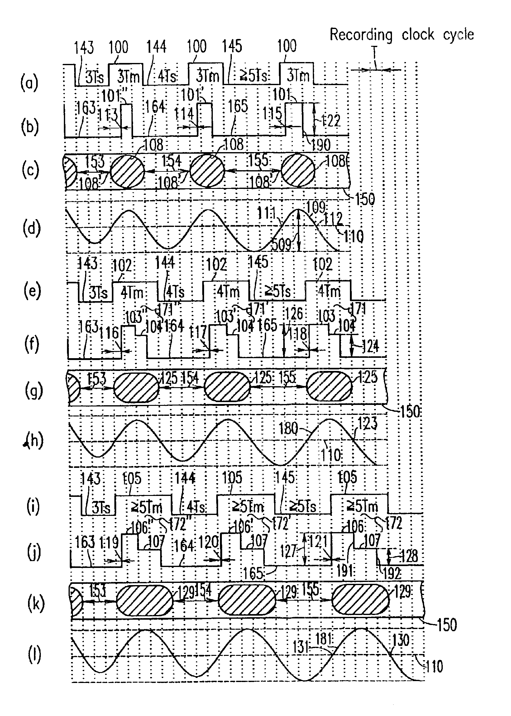
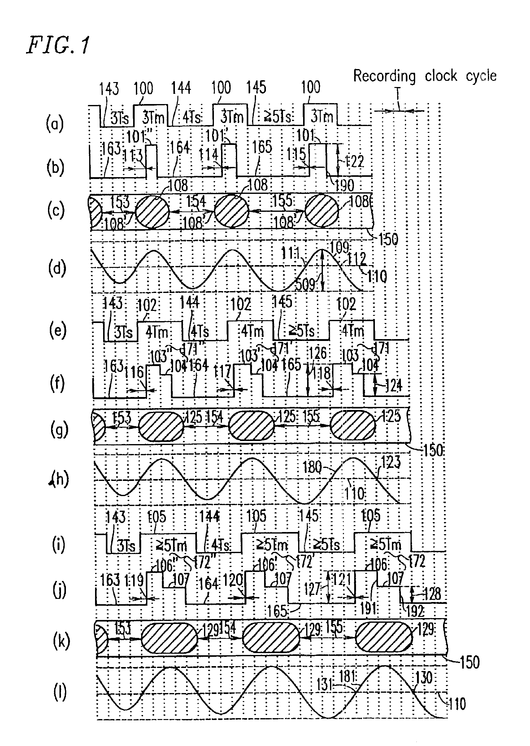
[0053]FIG. 1 is a diagram illustrating a method for recording / reproducing data on / from an optical disk and a method for adjusting a waveform (write strategy) and recording compensation parameters of a recording pulse for use in the data recording / reproducing method, which are described as Embodiment 1 of the present invention.

[0054]In FIG. 1, vertical dotted lines represent units of time and each division corresponds to one cycle T of the recording clock. From the top, FIG. 1(a) illustrates data in which a High-level signal 100 is allocated as a mark and Low-level signals 143, 144 and 145 are allocated as spaces, and illustrates a waveform of the recorded data 3 for use in the recording / reproducing apparatus 1000 of FIG. 3. The recorded data shown in FIG. 1(a) is formed of a series of the High-level signals 100 in the cases where lengths of spaces immediately before the shortest marks 108 of 3Tm are 3Ts, 4Ts and 5Ts or more.

[0055]FIG. 1(b) illustrates recording pulses ...

embodiment 2

(Embodiment 2)

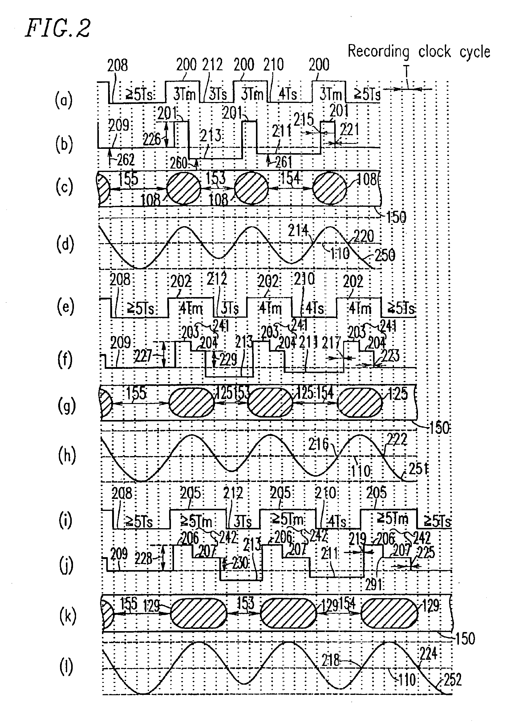
[0098]FIG. 2 is a diagram illustrating a method for recording / reproducing data on / from an optical disk and a method for adjusting the write strategy and recording compensation parameters of a recording pulse for use in the data recording / reproducing method, which are described as Embodiment 2 of the present invention. In the method illustrated in FIG. 2, same elements as those of Embodiment 1shown in FIG. 1 are denoted by same reference numerals, and therefore detailed description thereof is omitted.

[0099]FIGS. 2(a)-2(d) respectively illustrate recorded data, a recording pulse, recorded marks and an equalized reproduced signal in the case where shortest marks of 3Tm are recorded / reproduced. FIGS. 2(e)-2(h) respectively illustrate recorded data, a recording pulse, recorded marks and the equalized reproduced signal in the case where the long marks 125 of 4Tm are recorded / reproduced. FIGS. 2(i)-2(l) respectively illustrate recorded data, a recording pulse, recorded marks ...

embodiment 3

(Embodiment 3)

[0129]FIG. 8 is a diagram illustrating a method for recording / reproducing data on / from an optical disk and a method for adjusting the write strategy and recording compensation parameters of a recording pulse for use in the data recording / reproducing method, which are described as Embodiment 3 of the present invention. FIG. 8(a) illustrates recording pulses 810 and 811 respectively used for recording a long mark and a shortest mark using a recording method similar to Embodiments 1 and 2. FIG. 8(b) illustrates a long mark 820 and a shortest mark 821 respectively recorded by the recording pulse 810 and 811. The recording pulse for use in the recording / reproducing method of the present invention can also be performed and effective when preheat and cooling pulses described below are added thereto.

[0130]FIG. 8(c) illustrates an embodiment in which a preheat pulse 802 is added at an end position of the recording pulse 801 for forming a space 812. Since the preheat pulse 802 f...


PUM


Abstract

A shortest mark 108 is recorded with a single recording pulse. A long mark 125 is recorded with a two-stage pulse including a first-part pulse and a second-part pulse. In the case where each of positions 115 and 118 of front edges of the recording pulses is determined based on a relationship between a length of a space immediately before a mark and that of the mark itself so as to properly position the front edges of reproduced waveforms of all the mark lengths and each of positions of rear edges of the recording pulses of all the mark lengths is fixed so as to satisfy a prescribed relative relationship with an edge of a recording clock, power 122 of a recording pulse 101 of the shortest mark is determined so as to realize a proper rear edge position 112 of the reproduced waveform of the shortest mark and power 124 of a second-part pulse 104 is determined for each mark length so as to realize a proper rear edge position 123 of the reproduced waveform of the long mark.

Description

TECHNICAL FIELD[0001]The present invention relates to a method for recording / reproducing data on / from a rewritable optical disk using a mark edge recording method and a method for adjusting a waveform (write strategy) of a recoding pulse and recording compensation parameters for use in the data recording / reproducing method.BACKGROUND ART[0002]DVD-RAM is one of the rewritable optical disk standards. An optical disk in a DVD-RAM format having a capacity of 2.6 GB per side is already commercially available. A DVD-RAM disk having an increased capacity of 4.7 GB is currently under development. A recording method for use with a phase change-type optical disk, which is employed in the 4.7 GB DVD-RAM format, is described with reference to FIG. 16.[0003]FIG. 16(a) illustrates data 900 as an example of digital data to be recorded. The data 900 includes a High-level signal 901 of 11T (T denotes a recording clock cycle) and a Low-level signal 902 of 7T, and a High-level signal 903 of 3T. FIG. 1...

Claims


Application Information

Patent Timeline
IPC IPC(8): G11B20/14G11B7/125G11B7/0045G11B7/00G11B7/006
CPCG11B7/00456G11B20/1403G11B7/0062
Inventor FURUMIYA, SHIGERUSHOJI, MAMORU
Owner PANASONIC CORP
Why Eureka
Try Eureka