
Remote controlled inspection vehicle utilizing magnetic adhesion to traverse nonhorizontal, nonflat, ferromagnetic surfaces

a magnetic adhesion and inspection vehicle technology, applied in the direction of magnetic holding devices, electrical apparatus, dynamo-electric machine testing, etc., can solve the problems of inability or inadvisable direct human inspection, and achieve the effect of maximum conta

Inactive Publication Date: 2005-05-10
SIEMENS ENERGY INC
View PDF24 Cites 51 Cited by
  • Summary
  • Abstract
  • Description
  • Claims
  • Application Information

AI Technical Summary

Benefits of technology

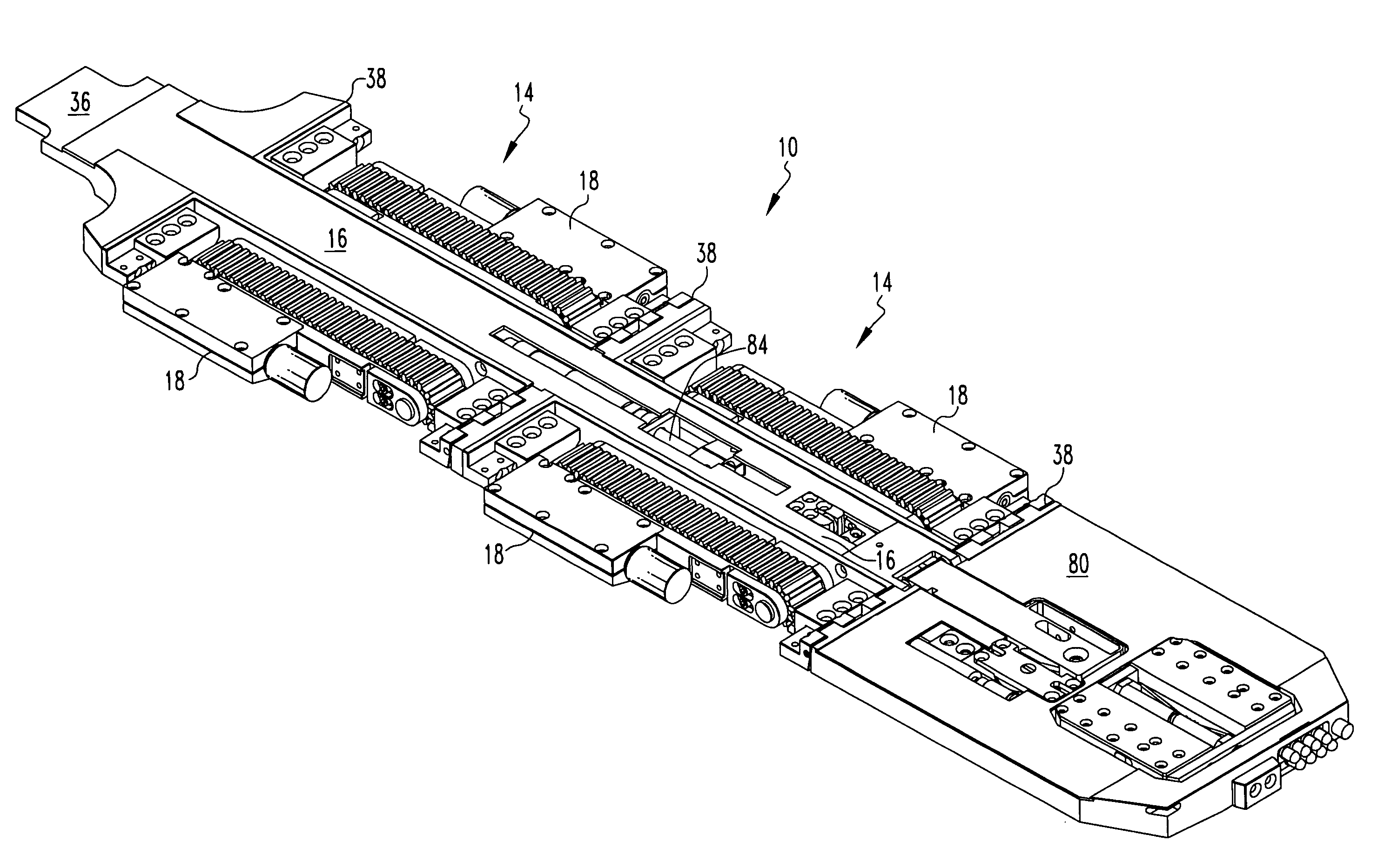
[0016]In use, the desired vehicle components may first be assembled. The modular construction of the vehicle permits the various components to be assembled in many different configurations, for example, any drive module may be placed anywhere on either the right or left side of the vehicle. A typical completed vehicle will include either one or two frames, depending on the size and / or ability to retain itself on a ferromagnetic surface. Drive modules with different size tracks may be utilized, depending upon the terrain and / or space limitations of the environment wherein inspection is desired. The tail may be mounted on the back end of the vehicle to assist in placing the vehicle in the desired location. The appropriate effector is mounted on the vehicle, depending upon the desired inspection to be performed. The vehicle is then inserted into the desired location, for example, between the rotor and stator of an electrical generator, wherein the vehicle may traverse either any horizontal surface, or any ferromagnetic surface to which the magnets inside the tracks may adhere. Power and control signals are supplied to the vehicle through cables extending from a remote controller to the vehicle, and data retrieved by the end effector are transmitted back to the remote controller for collection and analysis through additional cables. The encoders transmit signals back to the remote controllers corresponding to rotations of the motors, thereby permitting the position of the vehicle to be calculated based on the distance the vehicle will travel per rotation of the motor. Each drive module may be driven at different speeds when steering is desired, driving the tracks on one side of the vehicle at a faster speed than the tracks on the other side of the vehicle. If desired, it is possible to drive the tracks on one side of the vehicle one direction and the tracks on the other side of the vehicle the other direction, so that the vehicle may rotate about a stationary point. Additionally, an optional camera may assist in determining the location of the vehicle. The vehicle will traverse the various surfaces within the environment, perform the desired inspections, transmit the information back to the operators, and be retrieved from the environment.
[0019]It is a further aspect of the present invention to provide a remotely controlled inspection vehicle wherein the drive modules may pivot about the longitudinal axis, and the frames, effectors, and tail pivot with respect to each other about a transverse axis, thereby permitting maximized contact between each of the tracks and various irregular surfaces.

Problems solved by technology

It is frequently necessary to perform inspections of machinery, storage tanks, etc, where highly constrained entry points and / or environmental hazards make direct human inspection either impossible or inadvisable.

Method used


Image

  • Remote controlled inspection vehicle utilizing magnetic adhesion to traverse nonhorizontal, nonflat, ferromagnetic surfaces
  • Remote controlled inspection vehicle utilizing magnetic adhesion to traverse nonhorizontal, nonflat, ferromagnetic surfaces
  • Remote controlled inspection vehicle utilizing magnetic adhesion to traverse nonhorizontal, nonflat, ferromagnetic surfaces

Examples


Embodiment Construction

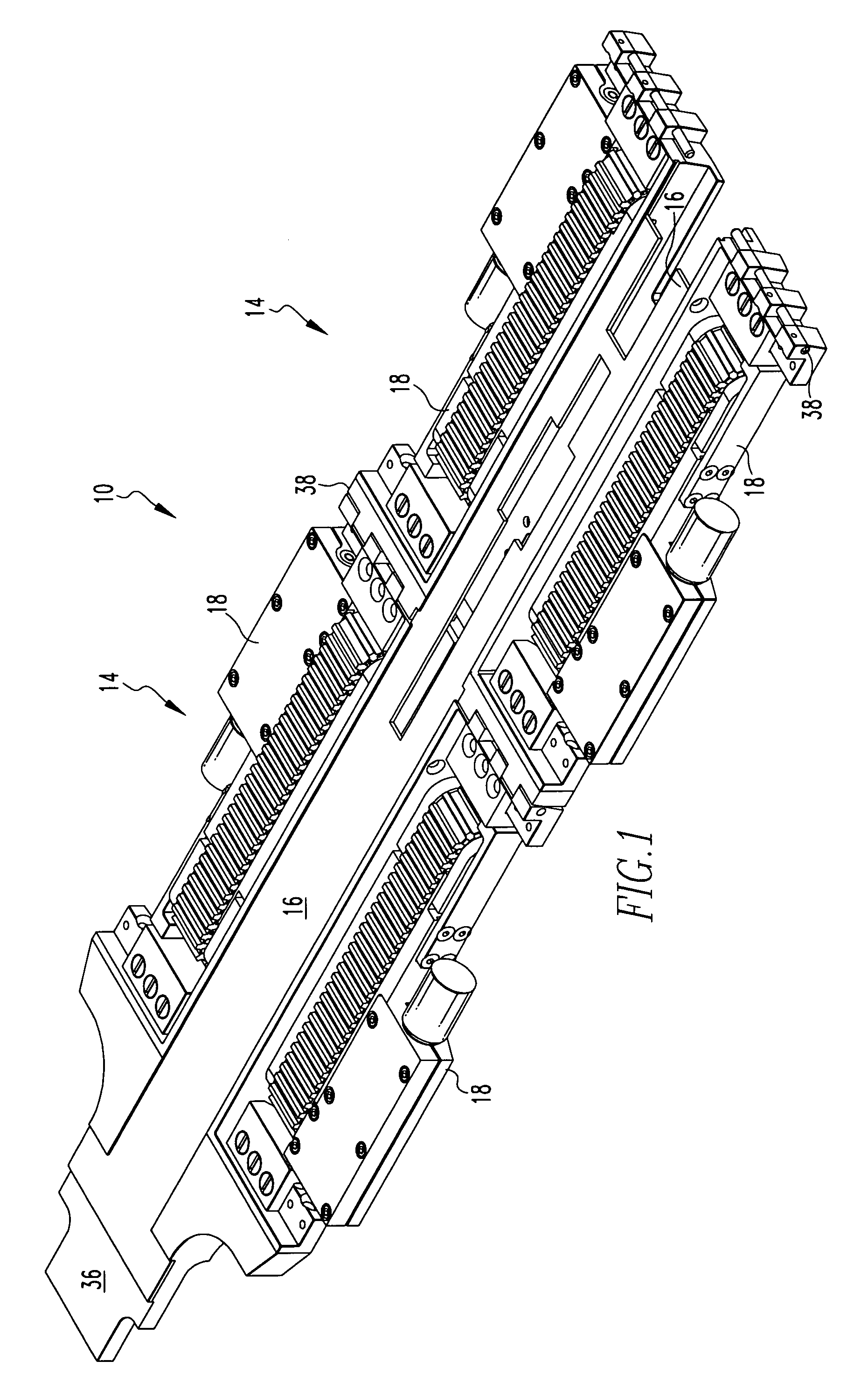
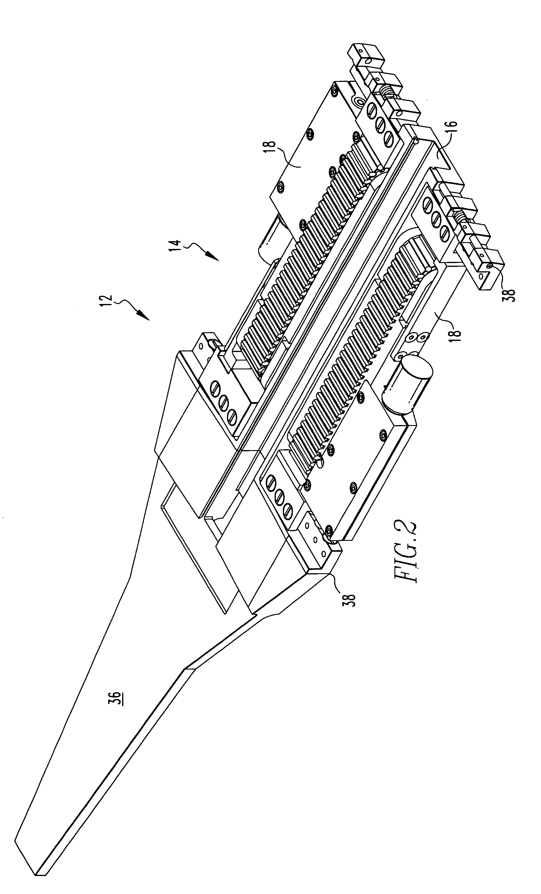
[0037]The preferred embodiments of the present invention are various configurations of a remote controlled inspection vehicle capable of traversing non-horizontal, ferromagnetic surfaces, and non-flat surfaces. Referring to FIGS. 1 and 2, a first vehicle embodiment 10 and second vehicle embodiment 12 are illustrated. The vehicle embodiments 10, 12 differ in the number of frame / drive module assemblies 14 present, with the vehicle 10 having two frame / drive module assemblies 14, and the vehicle 12 having a single frame / drive module assembly 14. Each frame / drive module assembly 14 includes a frame 16, having a drive module 18 on either side. Additionally, the vehicle embodiments 10,12 are illustrated with different tail sections 36 (described below), with the tail section 36 being user-selectable based on the desired use of the vehicle 10,12.

[0038]Referring to FIG. 3, the frame 16 preferably includes a central longitudinal beam 20, with a front transverse beam 22 and rear transverse bea...


PUM


Abstract

A remote controlled inspection vehicle provides interchangeable modules, permitting the vehicle to be easily configured to perform a wide variety of tasks. The vehicle includes at least one frame module having a pair of drive modules on either side. Each drive module includes a continuous track surrounding a permanent magnet, and is dimensioned and configured to pivot around its longitudinal axis. The frame modules are dimensioned and configured to be hingedly secured to other frame modules, end effectors including various sensors for performing inspections, and tail units to assist in placing the vehicle in the desired environment.

Description

CROSS REFERENCE TO RELATED APPLICATION[0001]This application is a continuation of U.S. application Ser. No. 09 / 995,182, filed Nov. 27, 2001 now U.S. Pat. No. 6,672,413, which claims the benefit of U.S. Provisional Patent Application Ser. No. 60 / 253,675, filed Nov. 28, 2000.BACKGROUND OF THE INVENTION[0002]1. Field of the Invention[0003]The present invention relates to remote controlled, unmanned inspection vehicles. More specifically, the present invention relates to inspection vehicles capable of entry into highly constrained spaces, and traversing nonhorizontal and / or nonflat ferromagnetic surfaces through magnetic adhesion to such surfaces.[0004]2. Description of the Related Art[0005]It is frequently necessary to perform inspections of machinery, storage tanks, etc, where highly constrained entry points and / or environmental hazards make direct human inspection either impossible or inadvisable. Examples include electrical generators and other machinery having highly constrained tr...

Claims


Application Information

Patent Timeline
Patent Type & Authority Patents(United States)
IPC IPC(8): B62D57/00B62D57/024
CPCB62D57/024H02N15/00G01R31/34
Inventor MOORE, CHARLES C.BAUER, JAMES A.FISCHER, MARK W.SILL, HARRY L.
Owner SIEMENS ENERGY INC
Learn More