
Electrode lead with multiple branches

a technology of electrode leads and branches, applied in the field of electrode leads, can solve the problems of tissue damage, patient pain, serious stress, etc., and achieve the effect of increasing the number of diagnostics

Inactive Publication Date: 2005-05-03
FLAMMANG DR DANIEL
View PDF17 Cites 39 Cited by
  • Summary
  • Abstract
  • Description
  • Claims
  • Application Information

AI Technical Summary

Benefits of technology

[0010]In an alternative embodiment of such an electrode arrangement the electrode-bearing branches have resilient structures as a shaping structure or splitting means, which are pre-shaped in such a way that by virtue of spring forces they cause the electrode-bearing branches to split up. The actuating means can then include a sliding sleeve which extends over the electrode line as far as the distal end thereof or into the proximity thereof and which at the proximal end of the electrode line has engagement means for displacing the sliding sleeve in the longitudinal direction of the electrode line. The sliding sleeve embraces the electrode-bearing branches at the distal end of the electrode line and holds them close together with the spring structure in a stressed condition. In that state the electrode line can be introduced for example into the atrium or the ventricle of a heart. The sliding sleeve is then retracted in the longitudinal direction of the electrode line and releases the electrode-bearing regions. The spring means of the electrode-bearing regions then cause the distal end of the electrode line to spread open into the individual branches. That then affords an electrode line whose electrode-bearing branches at the distal end are preferably in a shape such that one of the branches assumes a lateral position in the atrium of a heart and a second of the branches assumes a rectal position. An electrode shape of that kind permits timely and effective defibrillation even with weaker currents than were hitherto usual so that the defibrillation procedure involves a lower pain level for the patient.
[0016]After an element arrangement of that kind has been introduced into the atrium of a heart, such an electrode arrangement makes it possible for the atrium to be stimulated either successively in time-displaced relationship in a cascade-like procedure or simultaneously with bipolar voltage pulses, and in that way makes it possible to achieve a defibrillation effect with an extremely low level of stimulation energy. That affords the great advantage that defibrillation can be substantially pain-free for the patient.
[0017]The electrodes are preferably separately actuable and such that they are suitable both for receiving electrical signals from the heart and also for delivering electrical pulses to the heart. An electrode arrangement of that kind makes it possible to generate a large number of stimulation patterns but also to detect a large number of signals and symptoms which can be put to use for accurately determining the optimum stimulation pattern.
[0019]Preferably, in addition to the two or more branches already referred to above, the electrode arrangement has at least one further branch which is designed to assume a position in the ventricle or the atrium, respectively of heart and which has at least one electrode. An electrode arrangement of that kind increases the number of diagnostic and therapeutic options insofar as the ventricle and atrium electrodes can be combined with each individual one or any combination of the other electrodes.

Problems solved by technology

In that situation, in order rapidly to achieve termination of those life-threatening arrhythmia effects with a high level of certainty, relatively high voltages are conventionally applied and high levels of energy are supplied to the cardiac tissue, which in many cases results in tissue damage and serious stresses such as pain for the patient.
In addition, in relation to implantable units, the provision of those high voltages and high energy levels requires expensive apparatus implementation with special structural and insulating elements, in particular powerful batteries and capacitors.
Finally, electrode arrangements of large area were and still are used for transmitting the cardioversion energy to the cardiac tissue, and the production and implantation thereof involves a high cost level.

Method used


Image

  • Electrode lead with multiple branches
  • Electrode lead with multiple branches
  • Electrode lead with multiple branches

Examples


Embodiment Construction

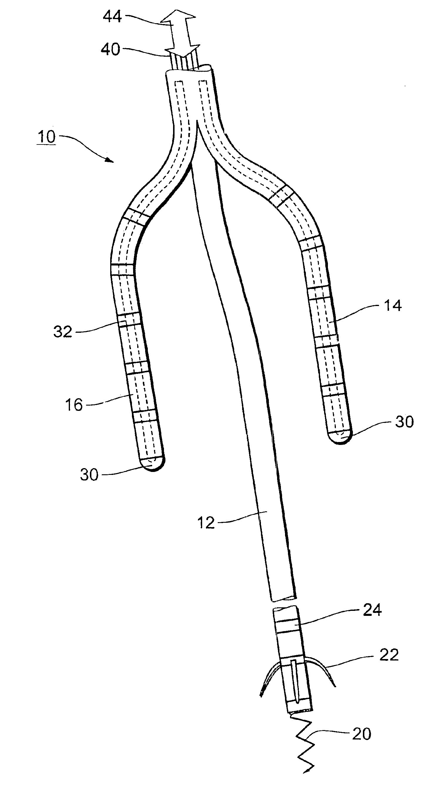
[0028]The distal end of an electrode line 10, as shown in FIG. 1, is split up into three branches, more specifically a ventricular branch 12, a septal branch 14 and a lateral branch 16.

[0029]The septal branch 14 and the lateral branch 16 each have six electrodes which are arranged equidistantly relative to each other and which are formed by conductive surface portions of the branches 14 and 16. The electrodes arranged at the free end of the two branches are in the form of tip electrodes 30 while the other electrodes which respectively follow the tip electrodes and in successive relationship with each other at a spacing of about one centimeter are in the form of ring electrodes 32. Each of the electrodes 30 and 32 can be individually connected by way of suitable signal and control lines 40 to a device for receiving electrical signals and for delivering voltage pulses with a defibrillator (not shown). Further-more, at the distal end of both the lateral and the septal branch 14 and 16 ...


PUM


Abstract

An electrode arrangement, in particular for the intracardial discharge of defibrillation pulses in the atrium of a heart, comprising an electrode line which in the region of its distal end has a plurality of electrically conductive surface portions as electrodes which can be electrically connected by way of the electrode line to an electrical pulsedischarging device such as defibrillator, wherein the electrode line is adapted to be split in the electrode-bearing region of its distal end into at least two respectively electrode-bearing branches.

Description

BACKGROUND OF THE INVENTION[0001]The invention concerns an electrode arrangement, in particular for the intracardial discharge of defibrillation pulses in the atrium or the ventricle of a heart, having an electrode line which in the region of its distal end has a plurality of electrically conductive surface portions as electrodes, which can be electrically connected by way of the electrode line to an electrical pulse-discharging device such as a defibrillator, cardioverter or pacemaker or the like.[0002]Certain cardiac palpitations or arrhythmia phenomena, including in particular ventricular and atrial fibrillation, but possibly also accelerating tachycardia phenomena which have not yet passed into the state of fibrillation are electrotherapeutically treated with good prospects of success by applying short-duration electrical pulses or shocks to the sensitive cardiac tissue.[0003]In that situation, in order rapidly to achieve termination of those life-threatening arrhythmia effects ...

Claims


Application Information

Patent Timeline
IPC IPC(8): A61N1/05A61N1/39
CPCA61N1/3918A61N1/0563
Inventor FLAMMANG, DANIEL
Owner FLAMMANG DR DANIEL
Learn More