
Encapsulation structure that acts as a multilayer mirror

a multi-layer mirror and encapsulation structure technology, applied in the direction of discharge tube/lamp details, discharge tube luminescnet screens, natural mineral layered products, etc., can solve the problems of reducing the lifetime of devices, and affecting the effect of light transmission

Inactive Publication Date: 2005-05-03
UNIVERSAL DISPLAY
View PDF18 Cites 108 Cited by
  • Summary
  • Abstract
  • Description
  • Claims
  • Application Information

AI Technical Summary

Benefits of technology

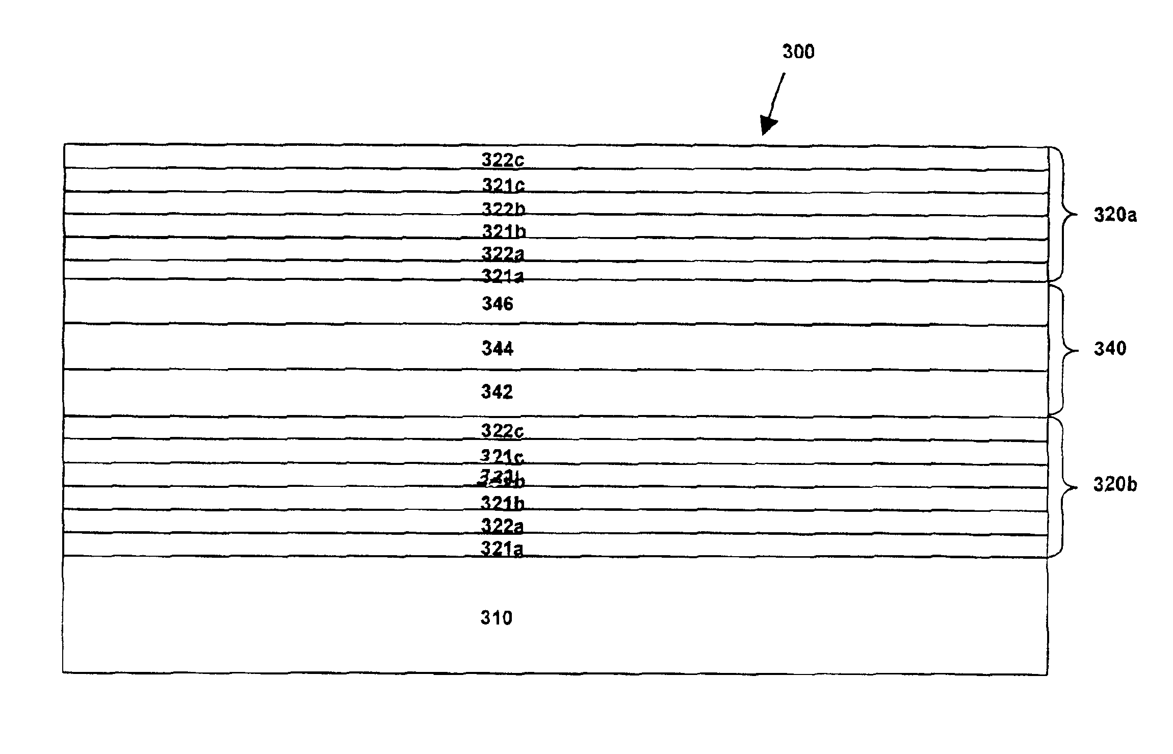
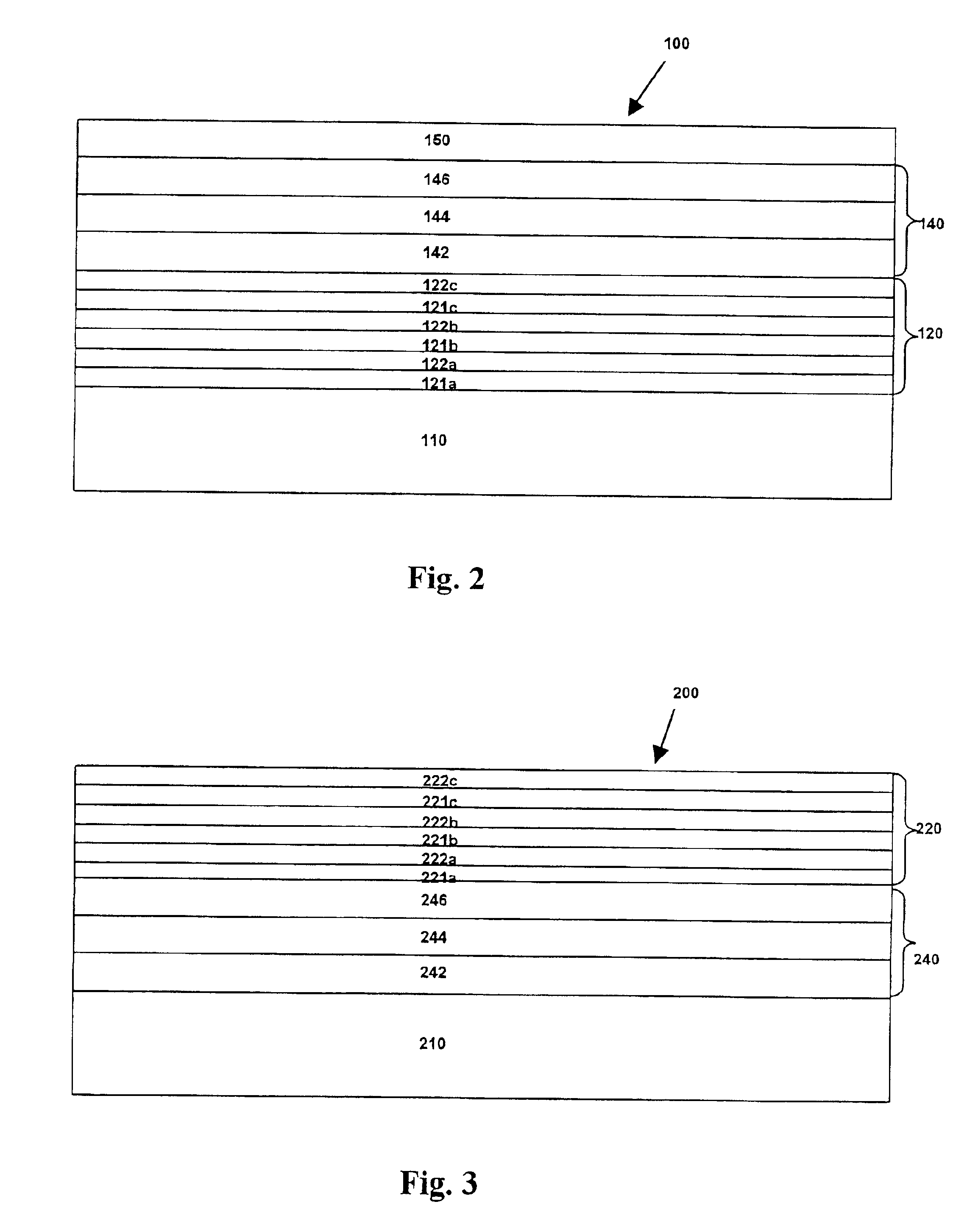
The present invention provides novel structures for OLED devices that simultaneously act as a multilayer mirror and as a barrier to harmful species in the exterior environment. These structures comprise a substrate, an OLED over the substrate, and a multilayer mirror over the substrate. The multilayer mirror is tuned to transmit light at a peak wavelength within the range of wavelengths emitted by the OLED and cooperates with the high-density layers to restrict transmission of water and oxygen. The thicknesses of the planarizing layers and high-density layers are selected to achieve both optical and barrier properties. The OLED can be a top-emitting, bottom-emitting, or transparent device.

Problems solved by technology

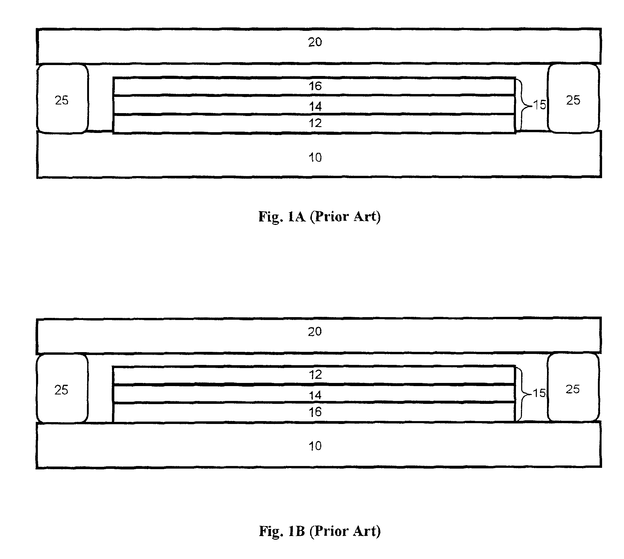
However, reactive metals and their interface with the organic material are susceptible to oxygen and moisture, which can severely limit the lifetime of the devices.
Moisture and oxygen are also known to produce other deleterious effects.

Method used


Image

  • Encapsulation structure that acts as a multilayer mirror
  • Encapsulation structure that acts as a multilayer mirror
  • Encapsulation structure that acts as a multilayer mirror

Examples


Embodiment Construction

[0024]The present invention now will be described more fully hereinafter with reference to the accompanying drawings in which preferred embodiments of the invention are shown. This invention may, however, be embodied in different forms and should not be construed as limited to the embodiments set forth herein.

[0025]As used herein, a “layer” of a given material includes a region of that material whose thickness is small compared to both its length and width. Examples of layers include sheets, foils, films, laminations, coatings, and so forth. As used herein a layer need not be planar, but can be bent, folded or otherwise contoured, for example, to at least partially envelop another component. A “layer” can contain two or more subordinate layers or “sublayers”.

[0026]Referring now to FIG. 2, an OLED structure generally designated by the numeral 100 is illustrated, which includes a substrate 110, a multilayer mirror (in this case, a quarter-wave stack 120), an OLED 140, and a cover regi...


PUM

PropertyMeasurementUnit
thicknessaaaaaaaaaa
wavelengthsaaaaaaaaaa
refractive indexaaaaaaaaaa

Abstract

The present invention is directed to novel structures for use in connection with OLED devices that simulaneously act as a multiplayer mirror and as a barrier to harmful species in the exterior environment. According to one embodiment of the invention, an OLED structure includes (a) a substrate; (b) an OLED over the substrate that includes (i) a first electrode, (ii) an emission region above the first electrode and (iii) a second electrode above the emission region, wherein the OLED emits light having a range of wavelengths upon being turned on; and (c) a multiplayer mirror over the substrate, the multiplayer mirror including an alternating series of (i) planarizing layers having a first refractive index and (ii) high-density layers having a second refractive index that differs from the first refractive index. The thicknesses of the planarizing layers and of the high-density layers in this embodiment are selected such that the multiplayer mirror is tuned to transmit light at a peak wavelength within the range of wavelengths emitted by the OLED. Moreover, the planarizing layers and the high-density layers cooperate to restrict transmission of water and oxygen.

Description

FIELD OF THE INVENTION[0001]The present invention relates to structures that protect organic light emitting devices from harmful species in the surrounding environment and to structures that reflect and transmit light that is emitted from such devices.BACKGROUND OF THE INVENTION[0002]Organic light emitting devices (“OLEDs”), including both polymer and small-molecule OLEDs, are potential candidates for a great variety of virtual-and direct-view type displays, such as lap-top computers, televisions, digital watches, telephones, pagers, cellular telephones, calculators and the like. Unlike inorganic semiconductor light emitting devices, organic light emitting devices are generally simple and relatively easy and inexpensive to fabricate. Also, OLEDs readily lend themselves to applications requiring a wide variety of colors and to applications that concern large-area devices.[0003]In general, two-dimensional OLED arrays for imaging applications are known in the art and typically include ...

Claims


Application Information

Patent Timeline
Patent Type & Authority Patents(United States)
IPC IPC(8): H01L51/52H01L51/50
CPCH01L51/5237H01L51/5262H01L51/5265H10K59/87H10K59/876H10K59/878H01L2224/05075H10K50/11H10K50/856H10K50/85H10K50/8445H10K50/852
Inventor WEAVER, MICHAEL STUART
Owner UNIVERSAL DISPLAY
Learn More