
Nail puller

a nail pulling and nailing technology, applied in the field of nail pulling tools, can solve the problems of limiting the function imposing geometric constraints on the design of the claw, and none successfully pulling nails with every attempt, so as to reduce the effort of pulling nails, improve the leverage of the nail pulling tool, and reduce the angularity of the pulling force

Inactive Publication Date: 2005-05-03
FORRESTER JOSEPH
View PDF10 Cites 6 Cited by
  • Summary
  • Abstract
  • Description
  • Claims
  • Application Information

AI Technical Summary

Benefits of technology

[0005]Another object is to improve leverage of a nail pulling tool.
[0007]Yet another object is to reduce the effort of pulling nails by reducing the angularity of the pulling force with respect to the axis of the nail.
[0008]It is also an object to provide a tool which accomplishes the foregoing objects, yet is of simple design to that it may be manufactured at a modest cost.

Problems solved by technology

Almost everyone has used a claw hammer to pull nails, and many are aware of the limitations of that tool for the function of pulling nails.
Despite the many configurations of the claw, none successfully pulls nails with every attempt.
This is so in part because the nail pulling structure (the claw) is integral with the nail driving structure (the head); this imposes geometric constraints on the design of the claw.
Other tools, such as pry bars having nail pulling features, suffer the same deficiencies, even though they may provide a longer stroke.
This angularity increases the friction between the nail shank and the hole, causing an unnecessary increase in the required pulling force.

Method used


Image

  • Nail puller
  • Nail puller
  • Nail puller

Examples


Embodiment Construction

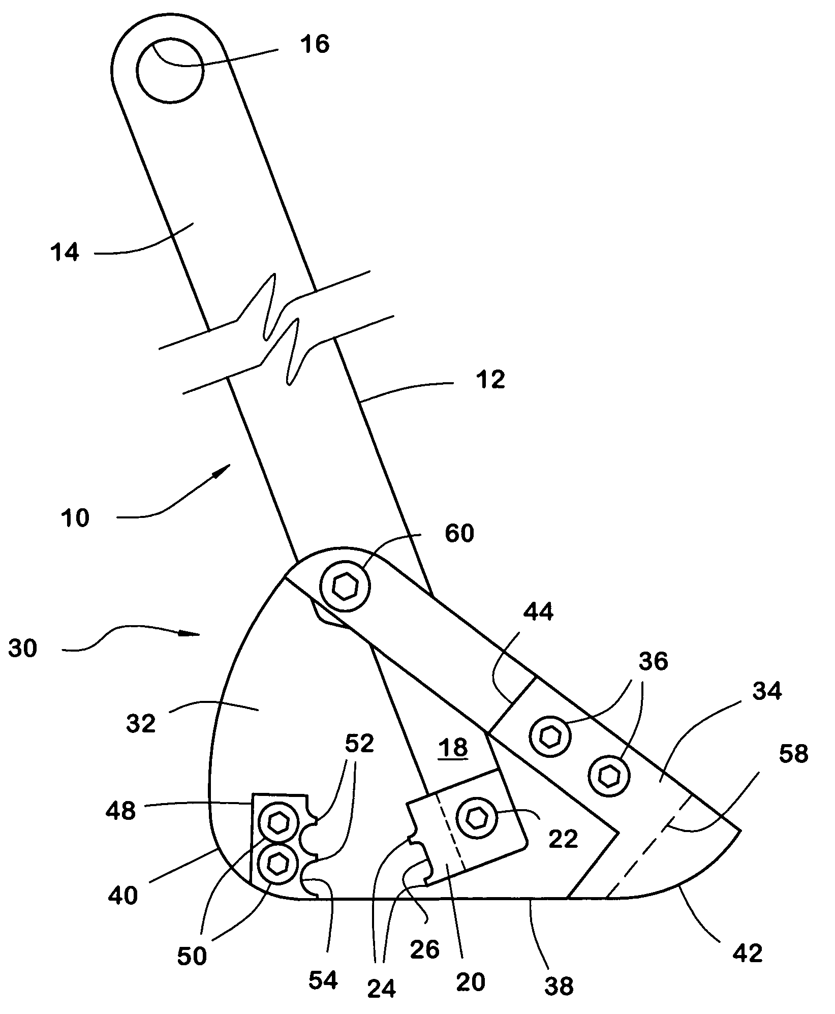
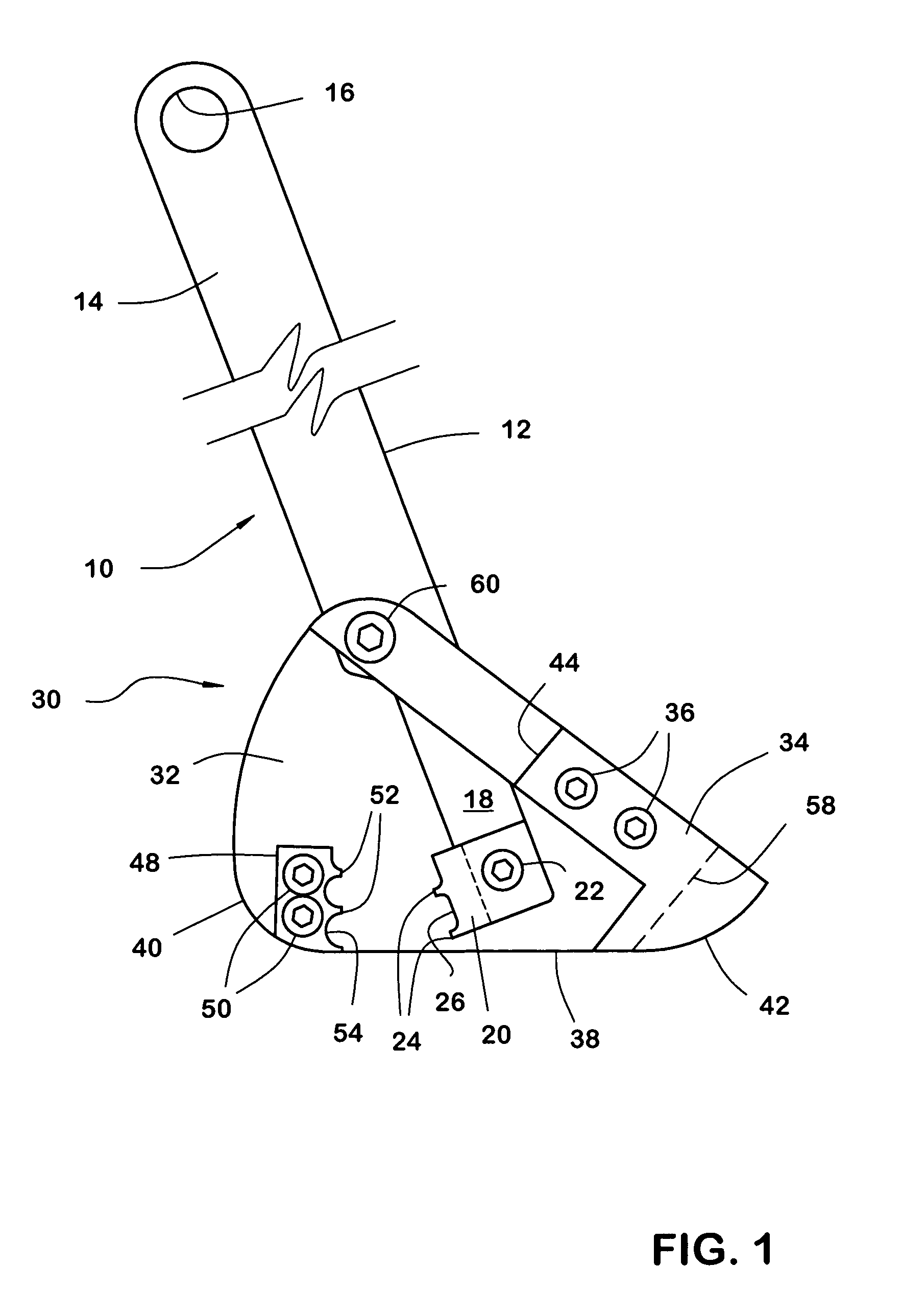
[0017]A nail puller embodying the invention (FIGS. 1–2) has two relatively movable parts: an arm assembly 10 and a base assembly 30 interconnected by a shoulder screw 60 which functions as a hinge pin.

[0018]The arm assembly 10 includes an arm 12 of suitable length, for example eighteen inches. The arm may have perforations (not illustrated) for decoration or for a practical purpose such as weight reduction or for facilitating attachment to a tool belt. The arm 12 has an upper end 14 fitted with a handle 16 to provide a comfortable grip, and a lower end 18 of reduced width.

[0019]A first gripping jaw 20 is affixed to the lower end of the arm by a removable fastener such as a machine screw 22. The jaw 20 has teeth 24 formed along its gripping surface. The groove 26 between the teeth is sufficiently deep to avoid bearing against the head of a nail grasped by the jaw. The shoulder screw 60 passes through a hole in the arm at an intermediate pivot point.

[0020]The base assembly 30 comprise...


PUM


Abstract

A nail puller comprises a base plate and a lever arm attached to the base plate. A pair of replaceable toothed gripping jaws are attached to the base plate and the lever arm respectively, the teeth being aligned so that the teeth pull a nail by its shank, rather than by its head, when force is applied to the lever.

Description

BACKGROUND OF THE INVENTION[0001]This invention relates to a nail puller of the type having relatively movable jaws for gripping a nail by its shank and a lever arm for exerting a pulling force on the nail.[0002]Of the many types of nail pulling tools, the most well known is the claw hammer. Almost everyone has used a claw hammer to pull nails, and many are aware of the limitations of that tool for the function of pulling nails. Despite the many configurations of the claw, none successfully pulls nails with every attempt. This is so in part because the nail pulling structure (the claw) is integral with the nail driving structure (the head); this imposes geometric constraints on the design of the claw. Also, because the claw is designed to engage the head of the nail, it is of little or no use when a nail's head has been broken off or badly damaged, or if the head is small, as with a finishing nail. And because the head must be engaged, the claw sometimes reaches its limit of travel ...

Claims


Application Information

Patent Timeline
Patent Type & Authority Patents(United States)
IPC IPC(8): B25C11/00
CPCB25C11/00
Inventor FORRESTER, JOSEPH
Owner FORRESTER JOSEPH
Learn More