Optical disk apparatus

a technology of optical disk and optical disk, applied in the direction of digital signal error detection/correction, instruments, recording signal processing, etc., can solve the problem of nonlinear variation of valu

Inactive Publication Date: 2005-04-26
TEAC CORP
View PDF12 Cites 8 Cited by
  • Summary
  • Abstract
  • Description
  • Claims
  • Application Information

AI Technical Summary

Benefits of technology

[0008]It is an object of the present invention to provide an optical disk apparatus capable of selecting an optimum recording power for any optical disk on which recording of data is desired.

Problems solved by technology

However, when the recording power increases beyond or exceeds this range, thermally distorted pits are formed in the optical disk and the variation in β value becomes nonlinear.

Method used


Image

  • Optical disk apparatus
  • Optical disk apparatus
  • Optical disk apparatus

Examples


Embodiment Construction

[0019]Preferred embodiments of the invention will be described below with reference to the drawings.

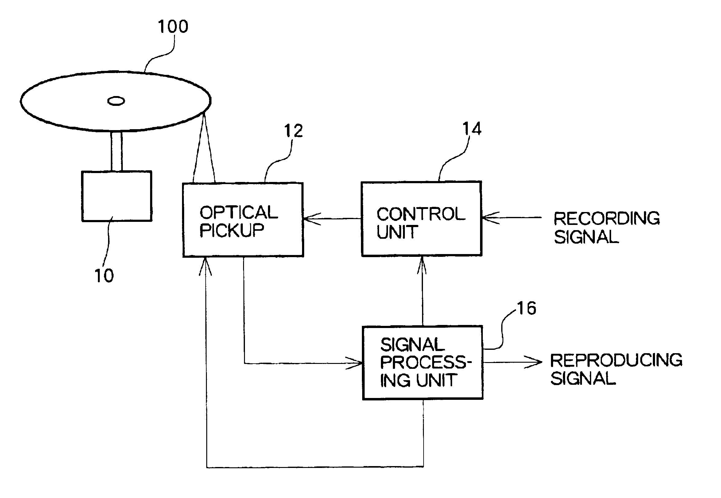
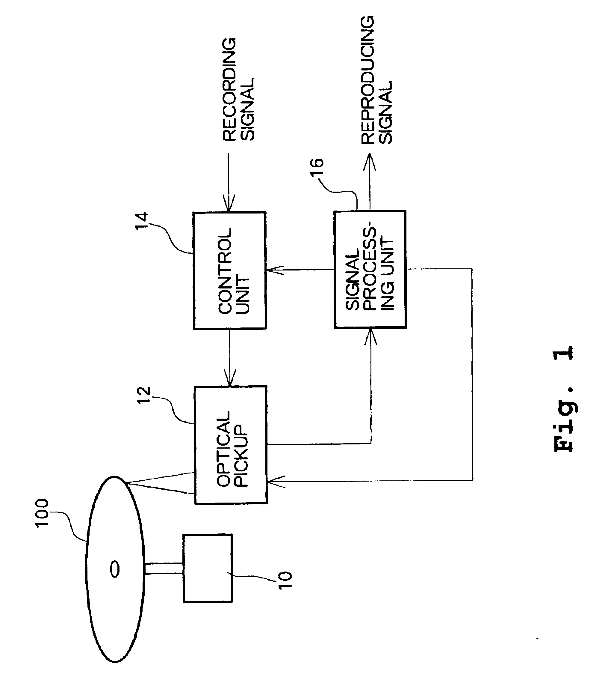
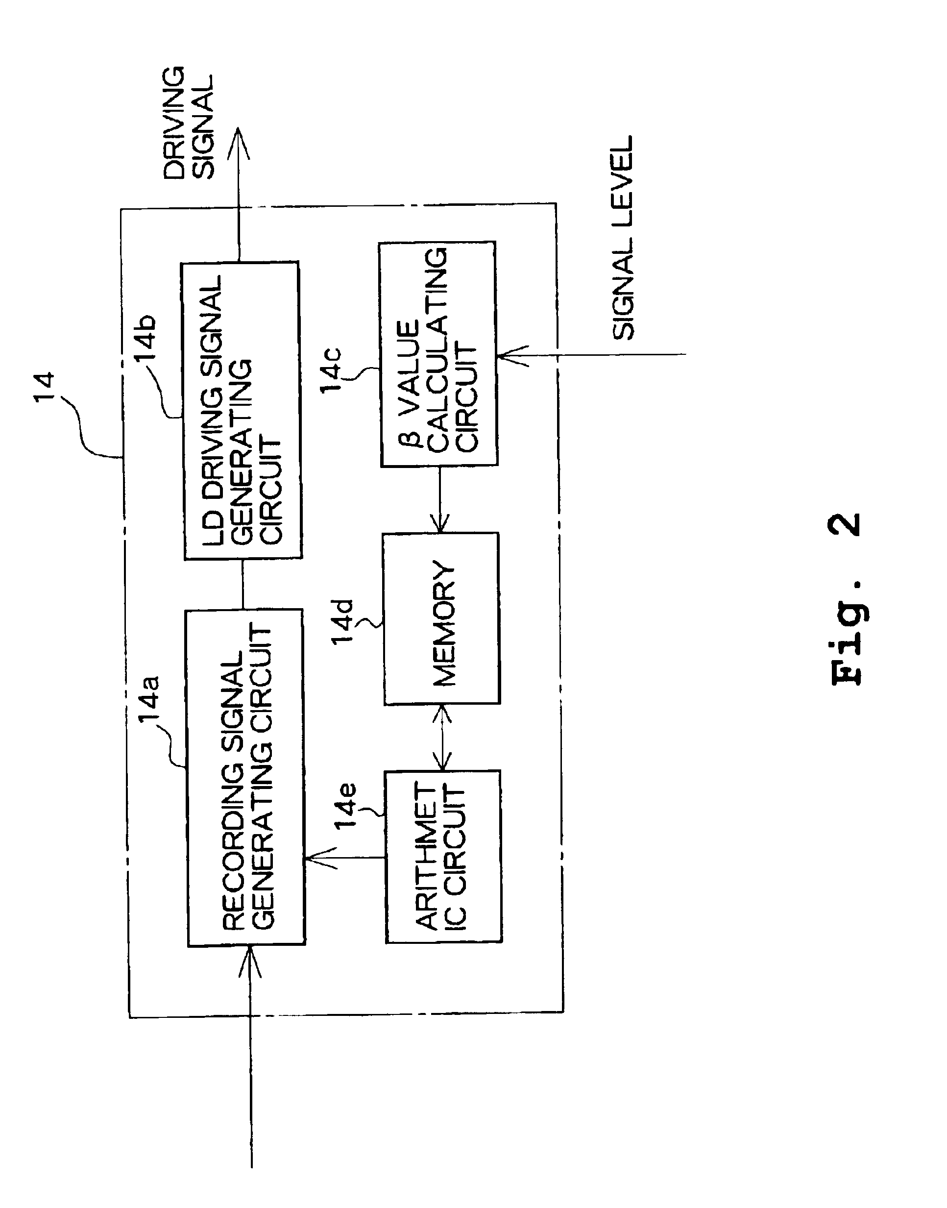
[0020]FIG. 1 shows a block diagram illustrating essential components of an optical disk apparatus according to one embodiment of the present invention. The optical disk apparatus comprises an optical pickup 12, a control unit 14, and a signal processing unit 16.

[0021]The optical pickup unit 12 irradiates laser light onto an optical disk 100, which is rotationally driven by a spindle motor 10, in order to record or reproduce data. The control unit 14 supplies a driving signal for recording, and data is recorded by forming a pit sequence having a period in the range of 3T to 11T (for DVD, 3T to 14T)on the optical disk 100. Further, the optical pickup unit 12 irradiates laser light having a reproducing power level onto an optical disk 100, and supplies the signal processing unit 16 with an RF signal reproduced from the reflected light.

[0022]The signal processing unit 16 demodulates the r...


PUM

PropertyMeasurementUnit
recording poweraaaaaaaaaa
βaaaaaaaaaa
power levelaaaaaaaaaa

Abstract

Recording power is optimized in an optical disk apparatus by recording a test signal on an optical disk while varying the recording power, and then determining a β value from a reproduced signal. A controller calculates a change in β value with respect to the recording power. A target β value is selected from those within the range wherein the β value varies linearly. The recording power by which the target β value is produced is selected as an optimum recording power for recording data on the optical disk. A modulation factor or parameters other than the β value may also be used as an indication of quality of reproduced signals.

Description

BACKGROUND OF THE INVENTION[0001]1. Field of the Invention[0002]The present invention relates generally to an optical disk apparatus, and more particularly to optimization of recording power.[0003]2. Description of the Related Art[0004]In optical disk apparatuses capable of recording data on a media like a CD-R (compact disk-recordable) disk, optimization of recording power using a process referred to as “OPC” (optimum power control) is commonly performed. In OPC, test signals are written onto a predetermined recording area of an optical disk while recording power is varied among a plurality of levels over a corresponding-number of frames, for example, 15 levels over 15 frames, and the test signal are reproduced for evaluation of a signal quality. As a measure of quality of a reproduced signal, usually a β value is used. β value is a parameter calculated using the equation β=(A+B) / (A−B), where A and B are peak and bottom voltages of the envelope of the reproduced RF signal, respecti...

Claims


Application Information

Patent Timeline
Patent Type & Authority Patents(United States)
IPC IPC(8): G11B7/125G11B7/007G11B7/0045G11B7/00G11B7/1267
CPCG11B7/1267G11B7/1263G11B7/0045
Inventor FUKUMOTO, MAKOTO
Owner TEAC CORP
Why Eureka
Try Eureka