
Connector for flexible printed circuit

Active Publication Date: 2005-04-26
JAPAN AVIATION ELECTRONICS IND LTD
View PDF7 Cites 21 Cited by
  • Summary
  • Abstract
  • Description
  • Claims
  • Application Information

AI Technical Summary

Benefits of technology

[0014]It is another object of the present invention to provide an FPC connector that allows an FPC to be inserted into an accurate position of the connector and to be held and engaged assuredly.

Problems solved by technology

However, in the connector according to the related art 1, a problem exists in that, since a direction in which the lever presses the FPC against the contact portion swings and is the same with that in which the FPC is flapped, when the FPC is flapped, the lever presses a contact point of the FPC against the contact to be opened, and to make a contact failure and so on result.
Furthermore, in the FPC connector according to the related art 2, a problem exists in that since an operation lever for pressing is disposed on a side opposite to the FPC insertion slot and a wall is disposed also on an upper side of the FPC insertion slot, the FPC insertion slot can be discerned with difficulty, resulting in inserting the FPC with difficulty.
Still furthermore, in the FPC connector according to the related art 3, a problem exists in that because of the wings disposed at both ends, when the FPC is laterally inserted from above, the wing portion and the FPC interfere each other to result in difficult insertion.

Method used


Image

  • Connector for flexible printed circuit
  • Connector for flexible printed circuit
  • Connector for flexible printed circuit

Examples


first embodiment

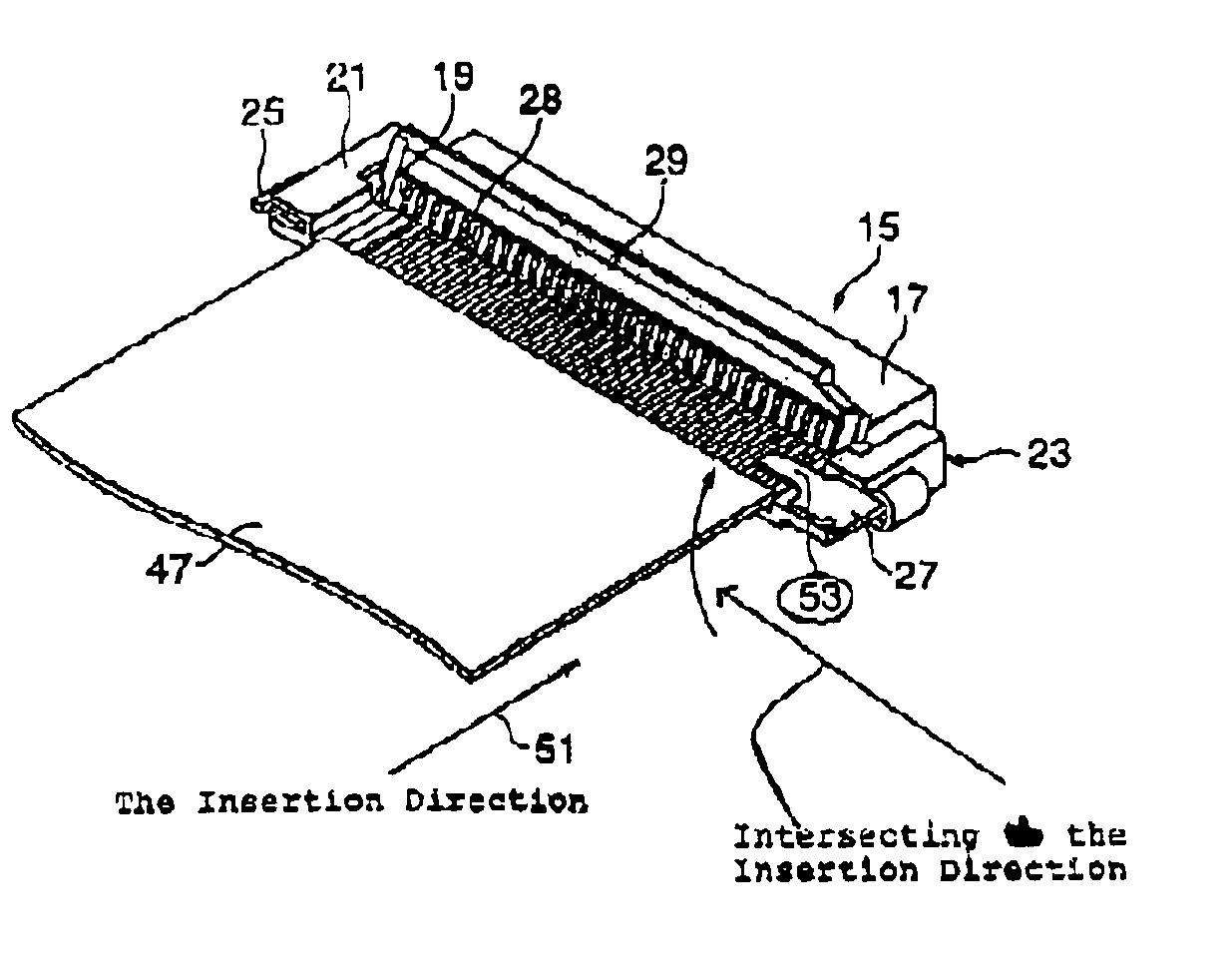
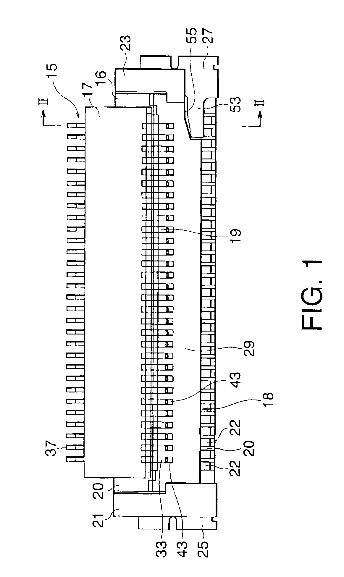
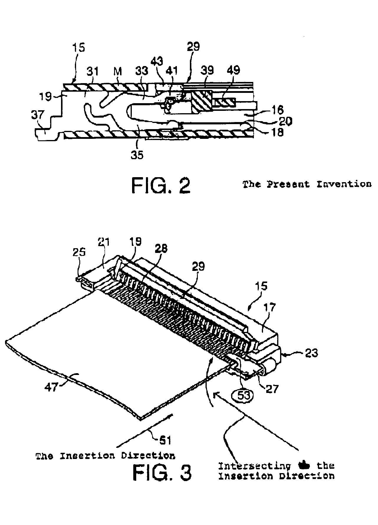
[0032]Referring to FIGS. 1 and 2, an FPC connector 15 includes a housing 17 made of a slender box-like insulating material. The housing 17 is provided with a plurality of conductive contacts 19 that is supported and arranged along a width direction. On both sides of the housing 17, through connection portions 16, attachment portions 21, 23 made of a wall portion are disposed. The attachment portions 21, 23 are provided with first and second members 25, 27 respectively made of a metal segment. The housing 17 is provided with an actuator 29, a pressurization member, which by swinging with a back side of the insertion slot 18 of the housing 17 as one axis, pressurizes a flexible printed circuit (hereinafter referred to as an FPC) that can open and close the insertion slot 18. In the invention, the open portion of the insertion slot 18 is a portion 28 that is exposed when the actuator 29 is opened.

[0033]The contact 19 is provided with a contact support portion 31 supported inside of th...

second embodiment

[0050]As shown in FIGS. 10 and 11, an FPC connector 73 has an attachment portion (wall portion) 75 thereto the second member 27 provided with the projection segment 53. The attachment portion is formed with a height h higher than or equal to a height H (H≦h) of the attachment portion (wall portion) 21 thereto the first member 25 is disposed. In such configuration, since the height of the attachment portion 75 is higher and furthermore the projection portion 53 is disposed, as shown in FIG. 10, even when the FPC 47 is inserted from an oblique lateral direction 77, connection can be established.

[0051]As shown in FIG. 13, an FPC connector 79 according to a third embodiment has a configuration similar to that according to the first embodiment except for differing in shapes of first and second members 81 and 83 and contacts 85 respectively made of metal segments. In each of the contact 85, a terminal portion for connecting to a base or the like is disposed exposed in the backward of the...


PUM


Abstract

A connector includes a contact, a housing, and an actuator. The housing holds and fixes the contact. The actuator presses an FPC, an object to be connected, and thereby connects the FPC and the contact. The connector further includes a first member that is fixed to the housing. The housing includes an insertion slot therein the FPC is inserted and thereto an open portion is formed. The first member includes a projection segment that projects toward the open portion of the insertion slot. The projection segment is provided with a chamfered portion on a side facing the open portion of the insertion slot.

Description

[0001]This invention claims priority to prior patent application JP 2002-174326, the disclosure of which is incorporated herein by reference.BACKGROUND OF THE INVENTION[0002]1. Field of the Invention[0003]The present invention relates to a connector for use in a flexible printed circuit that is mounted on a substrate and so on to connect thereto a flexible printed circuit or a flexible flat cable, hereinafter these are together referred to as a flexible printed circuit, FPC.[0004]2. Description of the Related Art[0005]So far, a connector of this kind is disclosed in JP-A-2000-48885, hereinafter referred to as a related art 1. The connector disclosed in the related art 1 in which an insertion direction of a flexible printed circuit (hereinafter referred to as an FPC including a flexible flat cable) is regarded as an anteroposterior direction includes a housing whose upper portion is opened; a plurality of contacts attached from a backside of the housing; and a lever that is supported...

Claims


Application Information

Patent Timeline
IPC IPC(8): H01R12/24H01R12/28H01R12/00H01R24/10H01R24/00H01R12/59H01R12/79
CPCH01R12/592H01R12/79H01R13/631
Inventor SAITO, YUICHIHIROSE, KUMI
Owner JAPAN AVIATION ELECTRONICS IND LTD
Learn More