
Compensation for timing variation in disc drives employing servo tracking systems

a technology of disc drives and timing marks, which is applied in the direction of maintaining head carrier alignment, digital recording, instruments, etc., can solve the problems of increasing the chance of false reading of timing marks, widening the search window of timing marks, and certain amount of misalignment between the track center of the disc and the spin axis of the spindle motor

Inactive Publication Date: 2005-04-19
SEAGATE TECH LLC
View PDF14 Cites 15 Cited by
  • Summary
  • Abstract
  • Description
  • Claims
  • Application Information

AI Technical Summary

Problems solved by technology

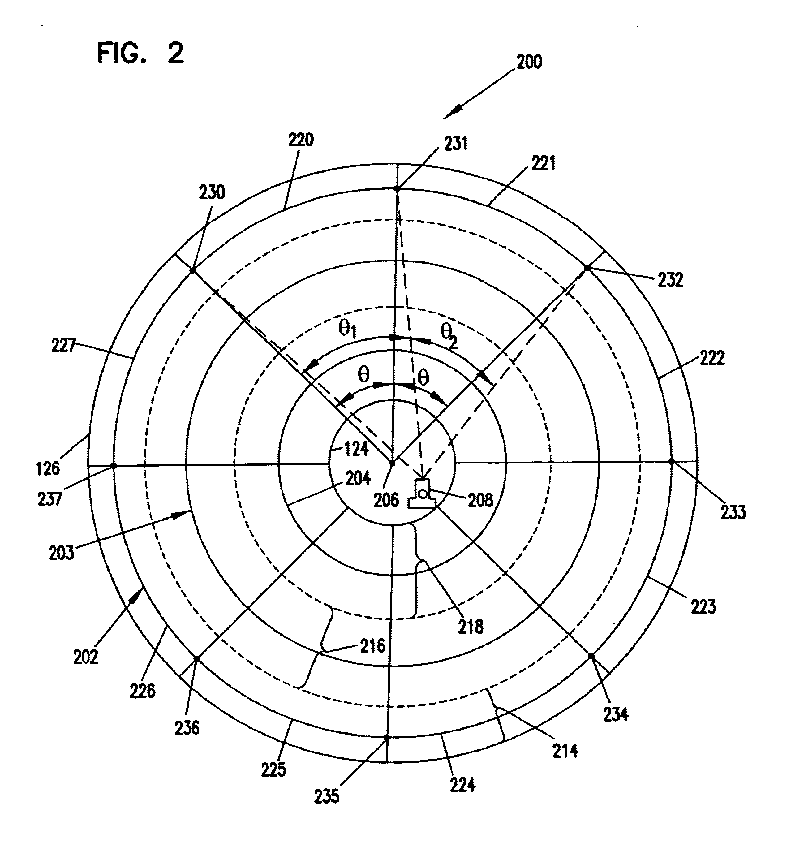
When such discs with pre-written tracks (pre-written discs) are mounted on a spindle motor of a disc drive, there is a certain amount of misalignment of the track center of the disc and the spin axis of the spindle motor.
Widening the timing mark search window is undesirable since it increases the opportunity of false reads of the timing marks.
Additionally, in drives that utilize embedded spindle motor control, variations in sample rate complicates the spindle motor control since the spindle motor controller is driven by a timing error that is related to variations in sample rate.

Method used


Image

  • Compensation for timing variation in disc drives employing servo tracking systems
  • Compensation for timing variation in disc drives employing servo tracking systems
  • Compensation for timing variation in disc drives employing servo tracking systems

Examples


Embodiment Construction

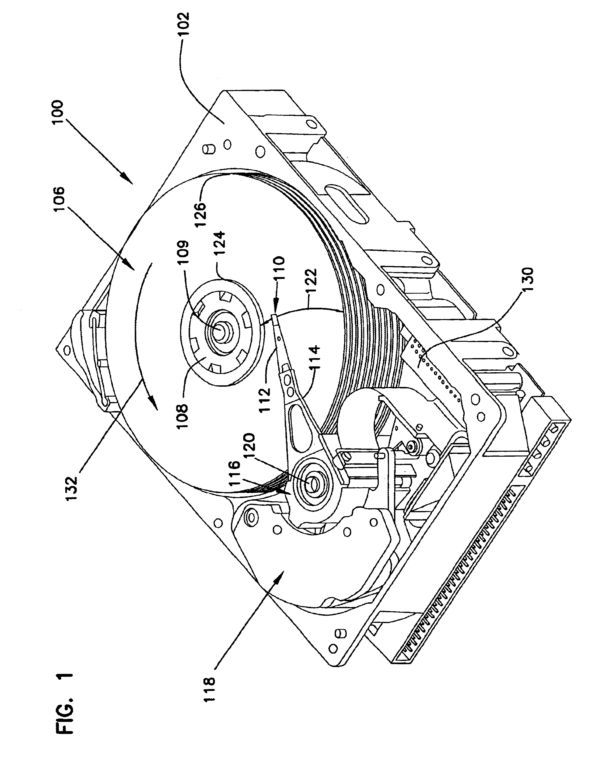
[0026]FIG. 1 is an isometric view of a disc drive 100 in which embodiments of the present invention are useful. Disc drive 100 includes a housing with a base 102 and a top cover (not shown). Disc drive 100 further includes a disc pack 106, which is mounted on a spindle motor (not shown in FIG. 1) by a disc clamp 108. Disc pack 106 includes a plurality of individual discs, which are mounted for co-rotation about central axis 109. Each disc surface has an associated disc head slider 110 which is mounted to disc drive 100 for communication with the disc surface. In the example shown in FIG. 1, sliders 110 are supported by suspensions 112 which are in turn attached to track accessing arms 114 of an actuator 116. The actuator shown in FIG. 1 is of the type known as a rotary moving coil actuator and includes a voice coil motor (VCM), shown generally at 118. Voice coil motor 118 rotates actuator 116 with its attached heads 110 about a pivot shaft 120 to position heads 110 over a desired da...


PUM


Abstract

An apparatus and method for compensating for variation in sample rate in a disc drive having a rotating disc and a head that is positioned over the rotating disc is provided. The disc includes at least one track that has multiple consecutive sectors. A sample rate value between timing marks of each pair of consecutive sectors of the multiple consecutive sectors is computed to obtain a sequence of sample rate values. A sequence of timing error values is computed as a function of the sequence of sample rate values and a nominal sample rate value. Data related to the sequence of timing error values is utilized to compensate for variation in sample rate values.

Description

CROSS-REFERENCE TO RELATED APPLICATION[0001]This application claims priority from U.S. Provisional Application No. 60 / 369,084 filed on Apr. 1, 2002 for inventors Reed D. Hanson, Timothy F. Ellis, Dustin M. Cvancara and Nathaniel B. Wilson and entitled “COMPENSATION FOR TIMING VARIATION IN DISK DRIVES HAVING SERVO TRACK ECCENTRICITY.”FIELD OF THE INVENTION[0002]The present invention relates generally to disc drive data storage systems. In particular, the present invention relates to compensation for timing variation in disc drives employing servo tracking systems.BACKGROUND OF THE INVENTION[0003]Disc drives read and write information along concentric tracks formed on discs. Each of the concentric tracks is divided into a plurality of sectors. Each of these sectors usually includes a servo field and a data field that are contiguous. To locate a particular track on a disc, disc drives typically use the embedded servo fields in the sectors. The embedded servo fields are utilized by a se...

Claims


Application Information

Patent Timeline
IPC IPC(8): G11B5/596G11B5/55
CPCG11B5/59627G11B5/5534
Inventor HANSON, REED D.ELLIS, TIMOTHY F.CVANCARA, DUSTIN M.WILSON, NATHANIEL B.
Owner SEAGATE TECH LLC
Learn More