Well abandonment plug

a technology for abandoning plugs and wells, which is applied in the direction of fluid removal, tubing catchers, borehole/well accessories, etc., can solve the problems of increasing the cost of abandonment, slow process, and high cos

Inactive Publication Date: 2005-04-19
GARRETT JONATHAN +2
View PDF27 Cites 27 Cited by
  • Summary
  • Abstract
  • Description
  • Claims
  • Application Information

AI Technical Summary

Benefits of technology

[0024]The tool body of the present invention can be retrieved. In the preferred embodiment, retainers are provided that hold the slips in a maximum extended position. However, when sufficient upward tension is applied to the wire line or slick line, a lower opening or recess provided at the lower end portion of the tool body enables a slight deformation inwardly of the lower end portion of the tool body so that the slips can move downwardly and cut the retainer. The retainer can be on o-ring, for example. The lower slips (and their springs) then fall into the well bore, separating from the tool body so that it can be retrieved.

Problems solved by technology

This process is relatively slow and expensive.
To counter this, an electric line set plug is sometimes set above the perforations to prevent the cement from dropping into the formation, adding significantly to the cost of the abandonment.

Method used


Image

  • Well abandonment plug
  • Well abandonment plug
  • Well abandonment plug

Examples


Embodiment Construction

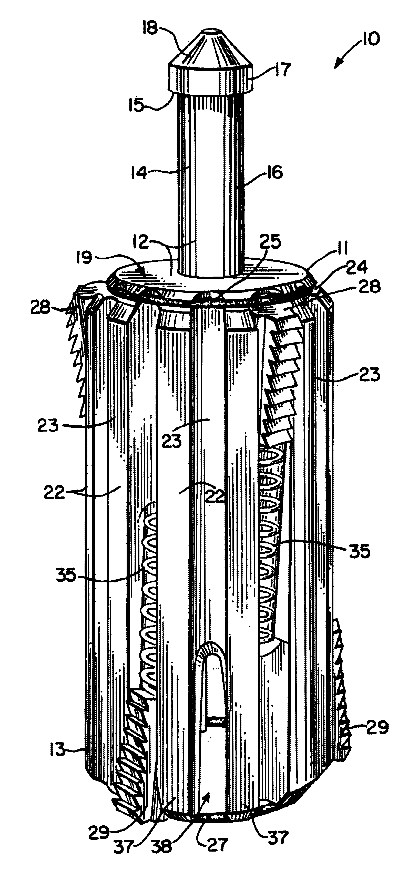
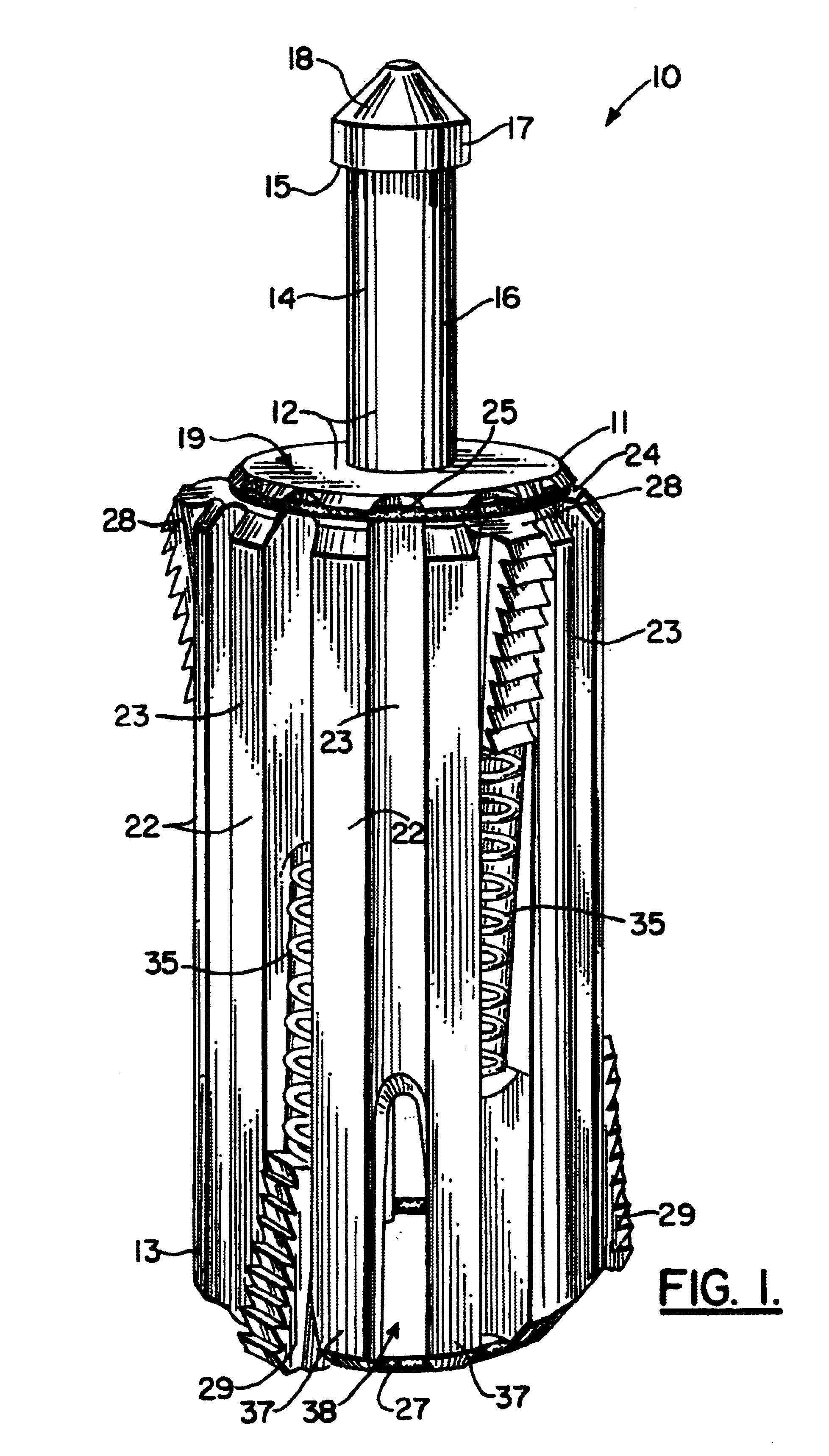
[0039]FIGS. 1, 5-6, 8 and 9-10 show the preferred embodiment of the apparatus 10 of the present invention. Well plug apparatus 10 provides a plug body 11 having upper end portion 12 and lower end portion 13. A neck fitting 14 is attached to upper end 12 at socket 20. Socket 20 provides internal threads that engage the externally threaded section 21 of neck fitting 14.

[0040]Neck fitting 14 has a transverse annular shoulder 15 with larger diameter cylindrical section 17 above it and smaller diameter cylindrical section 16 below it. Conical section 18 can be provided above cylindrical section 17. Upper end portion 12 of plug body 11 has a transverse surface 19 that communicates with socket 20.

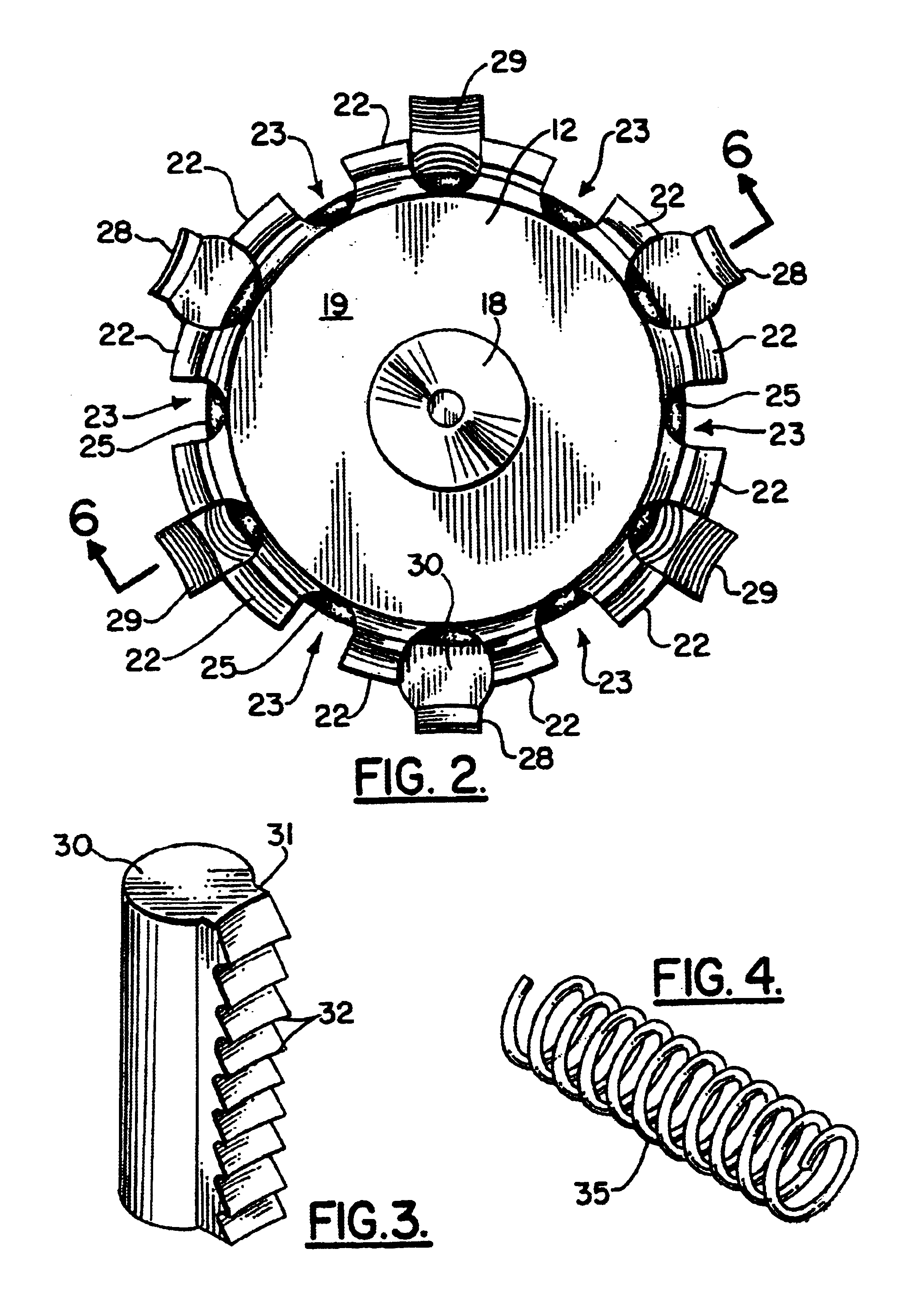
[0041]Plug body 11 has a plurality of ribs 22 with a plurality of grooves 23 spaced between the ribs 22. Each of the ribs 22 is longitudinally extending. The ribs 22 are circumferentially spaced and extend radially as shown in the top view of FIG. 2. Every other one of the grooves 23 communicates ...


PUM


Abstract

A method and apparatus of plugging and abandoning a well includes using a plug apparatus and installing bentonite elements in an oil well production casing having a bore. The plug apparatus is lowered into the production casing bore to a selected elevation using a slick line or the like. The apparatus has a tool body and slip dies that are movably mounted upon the tool body to move between extended and retracted positions. Afer the tool body is positioned at a selected location within the casing bore, tension is applied to the slick line to move the slip dies to an extended position wherein the slip dies engage the casing and secure the tool body in a desired location. The casing bore is then displaced with water above the tool body. Bentonite elements are then dumped into the water filled wellbore. The bentonite elements are allowed to swell to form a plug. The tool body can be retrieved from the casing bore if desired.

Description

CROSS-REFERENCE TO RELATED APPLICATIONS[0001]Priority of U.S. Provisional Patent Application Ser. No. 60 / 428,428, filed Nov. 21, 2002, incorporated herein by reference, is hereby claimed.STATEMENT REGARDING FEDERALLY SPONSORED RESEARCH OR DEVELOPMENT[0002]Not applicableREFERENCE TO A “MICROFICHE APPENDIX”[0003]Not applicableBACKGROUND OF THE INVENTION[0004]1. Field of the Invention[0005]The present invention relates to down hole oil well tools. More particularly, the present invention relates to a well abandonment plug apparatus that can be anchored at a selected position in a well and retrieved at a later time if desired.[0006]2. General Background of the Invention[0007]The present invention provides a plug that can be used in the Zonite (treated bentonite) abandonment technique of stripper wells. The design of the present invention is for a non-sealing plug to act as a base for the installation of the Zonite for the wells primarily in California and for a sealing plug for utilizat...

Claims


Application Information

Patent Timeline
Patent Type & Authority Patents(United States)
IPC IPC(8): E21B23/00E21B33/12E21B23/06E21B33/129E21B33/13E21B33/134
CPCE21B23/06E21B33/134E21B33/129
Inventor GARRETT, JONATHANLEROUGE, JOSEPHTAYLOR, MICHAEL
Owner GARRETT JONATHAN
Why Eureka
Try Eureka