
Procedure for fixing of toner on a print material and fixing device

a technology of toner and print material, which is applied in the direction of electrographic process equipment, instruments, optics, etc., can solve the problems of excess release oil being transferred onto the print material, contaminating the components of the printing machine and becoming deposited, and defects on the print material, so as to avoid contamination of the printing machine and the print material, clean image, and constant print image quality

Inactive Publication Date: 2005-04-12
EASTMAN KODAK CO
View PDF7 Cites 2 Cited by
  • Summary
  • Abstract
  • Description
  • Claims
  • Application Information

AI Technical Summary

Benefits of technology

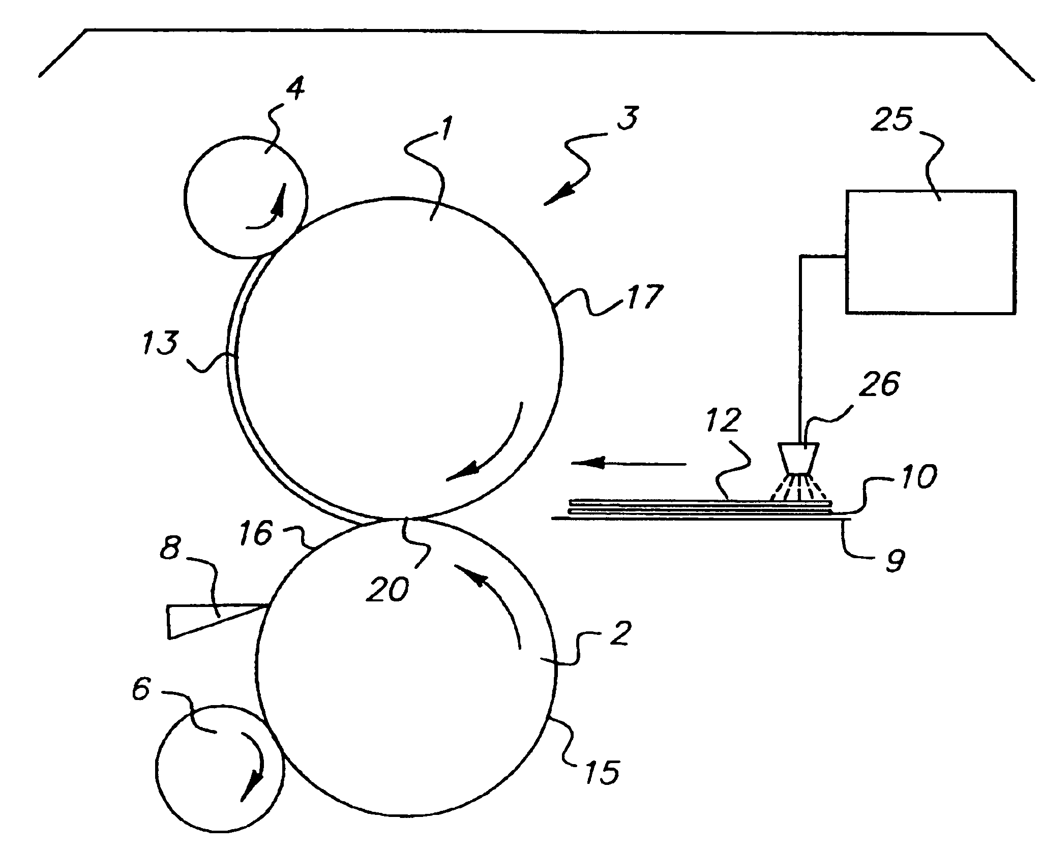
One object of the invention is to ensure that the fixing roller separates from the print material. A further object of the invention is to avoid contamination of the printing machine and the print material by release oil. A further object of the invention is to ensure a clean image, without defects, in a print machine. A further object of the invention is to obviate mechanical devices to apply release oil.
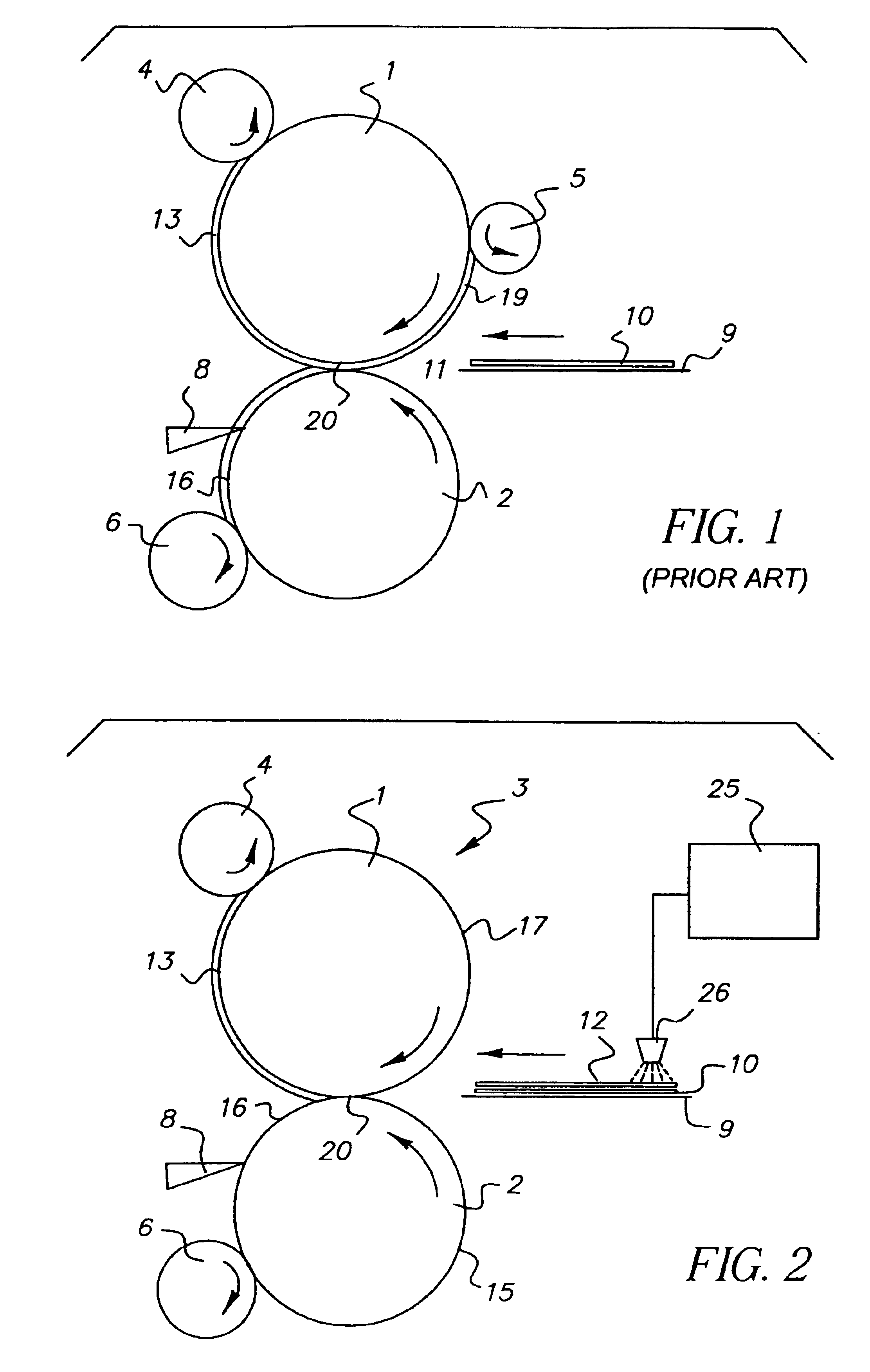
In one advantageous configuration of the invention, the amount of release oil of the layer is regulated depending on the desired gloss on the print material. In this way, the gloss of the image on the print material is adjusted in simple fashion.
In one advantageous embodiment, the amount of the release oil of the layer is regulated depending on the type of print material. Therefore, the invention is suited for situations where types of print material are changed, and ensures constant print image quality as well as a suitable, reliable removal of various print materials from the fixing roller with the print machine using differing types of print material. Further, contamination of the print machine by the release oil is avoided if a type of print material is used that requires less release oil than the previous type of print material for which the amount of release oil was suited.
It is advantageous to have the layer comprised of small capsules in which there is fixing material, thus improving the capacity to provide appropriate doses of the fixing material.

Problems solved by technology

One disadvantage is that the release oil is provided in inexact doses, leading to excess release oil being transferred onto the print material.
Excess release oil is transported through the printing machine, contaminating components of the printing machine and becoming deposited on it, particularly on the blade for the removal of release oil.
From the components contaminated with release oil, the release oil can get onto the print material and cause defects on the print material, e.g. by smearing the image.

Method used


Image

  • Procedure for fixing of toner on a print material and fixing device
  • Procedure for fixing of toner on a print material and fixing device
  • Procedure for fixing of toner on a print material and fixing device

Examples


Embodiment Construction

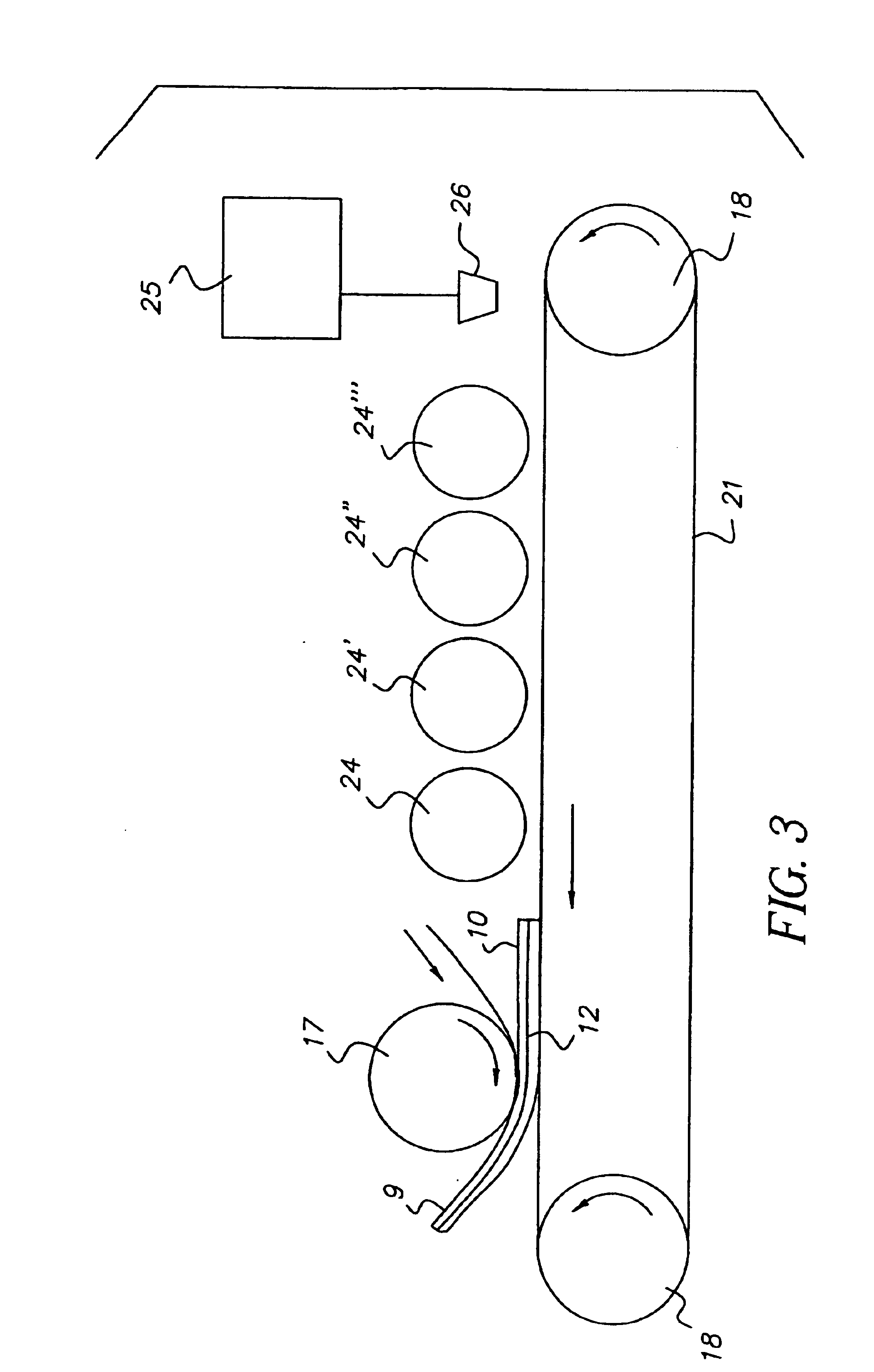
FIG. 1 is a schematic view of the essential components of a fixing device in a state-of-the-art printing machine with a fixing roller 1, which turns about its axis in the manner shown. Set in opposition to fixing roller 1 is a back-up pressure roller 2, which touches fixing roller 1, and rolls in a direction opposite to it. Between fixing roller 1 and back-up pressure roller 2, a print material 9 is transported in the direction of the straight arrow. Print material 9 has a toner layer 10 on its upper side, which represents a print image. Toner layer 10 is transferred in printing stages before fixing on the print material 9; after transfer (application), the toner is not sufficiently fixed to the print material. Therefore, print material 9 with toner layer 10 is moved between fixing roller 1 and back-up pressure roller 2, thus causing toner layer 10 to be secured onto print material 9, aided by pressure and heat, and becoming fixed to it. After print material 9 with toner layer 10 mo...


PUM


Abstract

An apparatus and procedure for the separation of a fixing roller from the print material, wherein, contamination of the print machine and the print material by release oil is avoided. A toner layer is applied to the printing material and, at minimum, a release material layer is directly applied to the printing material, upstream of the fixing roller, which makes possible reliable separation of the fixing roller from the print material.

Description

FIELD OF THE INVENTIONThe invention concerns fixing toner on print material wherein a layer applied directly to print material makes for reliable separation of fixing roller from print material.BACKGROUND OF THE INVENTIONIn the printing industry, various printing procedures are used, with variously configured printing machines. One factor common to the various printing procedures is that toner is applied to print material and then fixed to it. Various state-of-the-art solutions have been proposed for fixing toners to print material; one typical solution is to have a heated fixing roller come into rolling contact with the print material, and the toner is then fixed on the print material by pressure and heat. To facilitate detachment of the fixing roller from the print material, the fixing roller is provided with a release oil. The fixing oil is applied using rollers onto the fixing roller, with the rollers making contact with the fixing roller. Setting the dosage of the release oil d...

Claims


Application Information

Patent Timeline
Patent Type & Authority Patents(United States)
IPC IPC(8): G03G15/20
CPCG03G15/6585G03G15/2025G03G2215/0081G03G2215/00805
Inventor MANLEITNER, MARKUS PETER
Owner EASTMAN KODAK CO
Learn More