
Method for encoding an input signal

Inactive Publication Date: 2005-04-12
NIELSEN COMPANY US LLC THE A DELAWARE LIMITED LIABILITY
View PDF148 Cites 66 Cited by
  • Summary
  • Abstract
  • Description
  • Claims
  • Application Information

AI Technical Summary

Problems solved by technology

It will be recognized that, because ancillary codes are preferably inserted at low intensities in order to prevent the ancillary code from distracting a listener of program audio, such ancillary codes may be vulnerable to various signal processing operations.
For example, although Lee et al. discuss digitized audio signals, it may be noted that many of the earlier known approaches to encoding an audio signal are not compatible with current and proposed digital audio standards, particularly those employing signal compression methods that may reduce the signal's dynamic range (and thereby delete a low level ancillary code) or that otherwise may damage an ancillary code.
Unlike the analog domain, where repeated copying of music and video stored on media, such as tapes, results in a degradation of quality, digital representations can be copied without any loss of quality.
The main constraints preventing illegal reproductions of copyrighted digital material is the large storage capacity and transmission bandwidth required for performing these operations.
A problem with the “fragile” ancillary code is that it is fragile and may be difficult to receive even when there is no unauthorized compression / decompression.

Method used


Image

  • Method for encoding an input signal
  • Method for encoding an input signal
  • Method for encoding an input signal

Examples


Embodiment Construction

Audio signals are usually digitized at sampling rates that range between thirty-two kHz and forty-eight kHz. For example, a sampling rate of 44.1 kHz is commonly used during the digital recording of music. However, digital television (“DTV”) is likely to use a forty eight kHz sampling rate. Besides the sampling rate, another parameter of interest in digitizing an audio signal is the number of binary bits used to represent the audio signal at each of the instants when it is sampled. This number of binary bits can vary, for example, between sixteen and twenty four bits per sample. The amplitude dynamic range resulting from using sixteen bits per sample of the audio signal is ninety-six dB. This decibel measure is the ratio between the square of the highest audio amplitude (216=65536) and the lowest audio amplitude (12=1). The dynamic range resulting from using twenty-four bits per sample is 144 dB. Raw audio, which is sampled at the 44.1 kHz rate and which is converted to a sixteen-bi...


PUM


Abstract

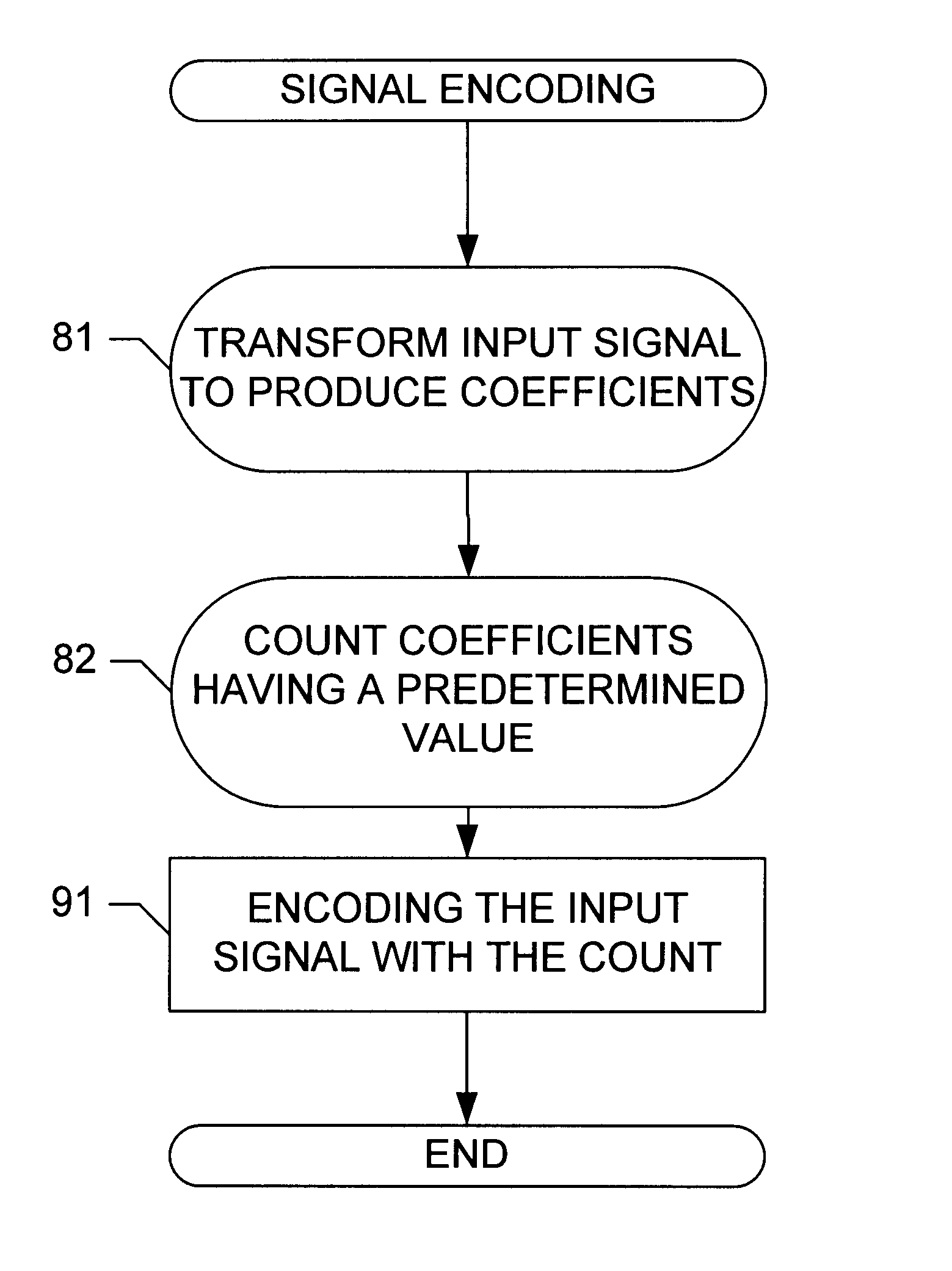
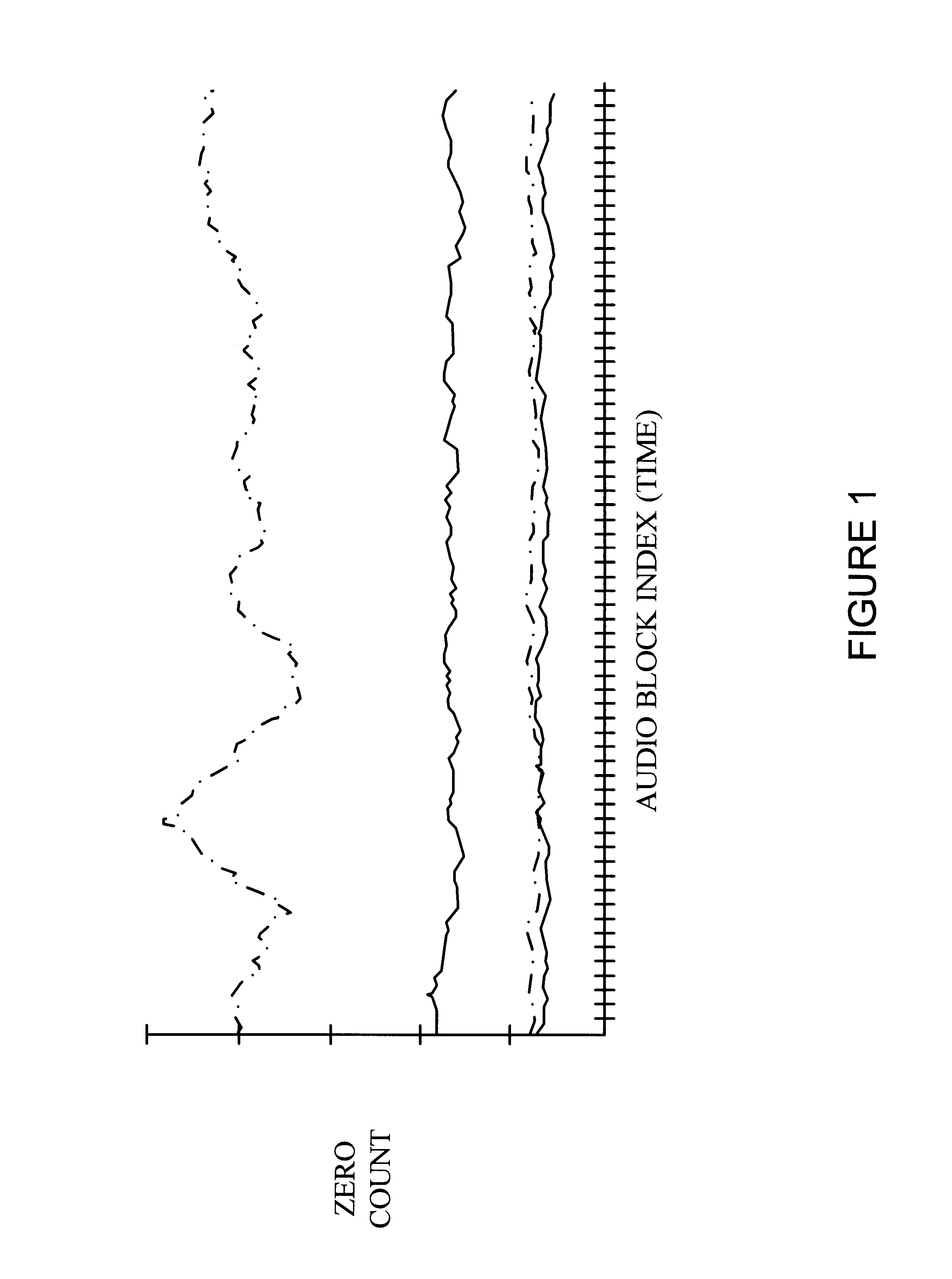
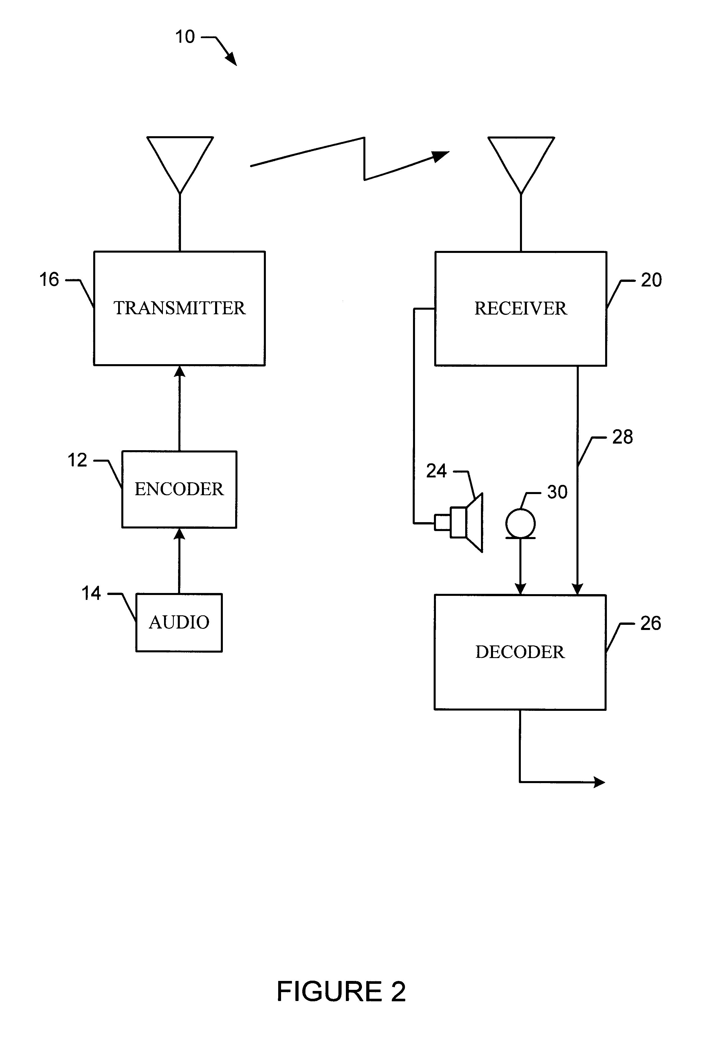
An encoder transforms at least a portion of a signal, counts the resulting transform coefficients having a zero value, and encodes the signal with the zero count. A decoder decodes the signal in order to recover the zero count. The decoder may also determine its own zero count of the signal as received and may compare the zero count that it determines to the recovered zero count. The decoder may be arranged to detect compression / decompression based upon results from the comparison, and / or the decoder may be arranged to prevent use of a device based upon results from the comparison.

Description

TECHNICAL FIELD OF THE INVENTIONThe present invention relates to the detection of signals, such as audio streams, which have been modified.BACKGROUND OF THE INVENTIONVideo and / or audio received by video and / or audio receivers have been monitored for a variety of reasons. For example, the transmission of copyrighted video and / or audio is monitored in order to assess appropriate royalties. Other examples include monitoring to determine whether a receiver is authorized to receive the video and / or audio, and to determine the sources and / or identities of video and / or audio.One approach to monitoring video and / or audio is to add ancillary codes to the video and / or audio at the time of transmission or recording and to detect and decode the ancillary codes at the time of receipt by a receiver or at the time of performance. There are many arrangements for adding an ancillary code to video and / or audio in such a way that the added ancillary code is not noticed when the video is viewed on a mo...

Claims


Application Information

Patent Timeline
IPC IPC(8): G10L19/00G10L19/02
CPCG10L19/0212
Inventor SRINIVASAN, VENUGOPAL
Owner NIELSEN COMPANY US LLC THE A DELAWARE LIMITED LIABILITY
Learn More