
Anti-malfunction mechanism for variable output device

a technology of output device and anti-malfunction, which is applied in the direction of camera body details, instruments, cameras, etc., can solve the problems of undue change of parameters of electric apparatus and voice level against the intention of users, and achieve the effect of reducing both cost and weight, and reducing the durability of the output devi

Inactive Publication Date: 2005-04-12
PANASONIC CORP
View PDF7 Cites 4 Cited by
  • Summary
  • Abstract
  • Description
  • Claims
  • Application Information

AI Technical Summary

Benefits of technology

"The invention is about a mechanism to prevent the accidental movement of an operating unit against the user's will in a variable output device. The mechanism includes a mounting unit, an operating unit, a holding member, and an elasticity applier. The operating unit is mounted on the mounting unit and can be moved in the direction of the operating shaft. The holding member is positioned opposite the operating unit and has an operating hole through which the operating unit passes. The elasticity applier is positioned between the operating unit and the holding member and elastically pushes the operating unit into contact with the holding member. This prevents the malfunction of the electricity regulator in off state. A buffer member can be added to further secure the operating unit and seal the gap between the operating unit and the operating hole of the holding member. The elasticity applier can be a coil spring or a corrugated washer and can be protected by a protective member. A metal sheet can be added to prevent damage to the operating unit."

Problems solved by technology

Under an incidental external force or with an inadvertent operation of the operating unit 5 by the user, the operating unit 5 is undesirably rotated against the will of the user, with the inconvenient result that the parameters of the electric apparatus are unduly changed.
In a single-unit video camera recorder, for example, a malfunction of the operating unit of a variable output device for adjusting the voice level may change the voice level against the intention of the user during the recording operation.

Method used


Image

  • Anti-malfunction mechanism for variable output device
  • Anti-malfunction mechanism for variable output device
  • Anti-malfunction mechanism for variable output device

Examples


first embodiment

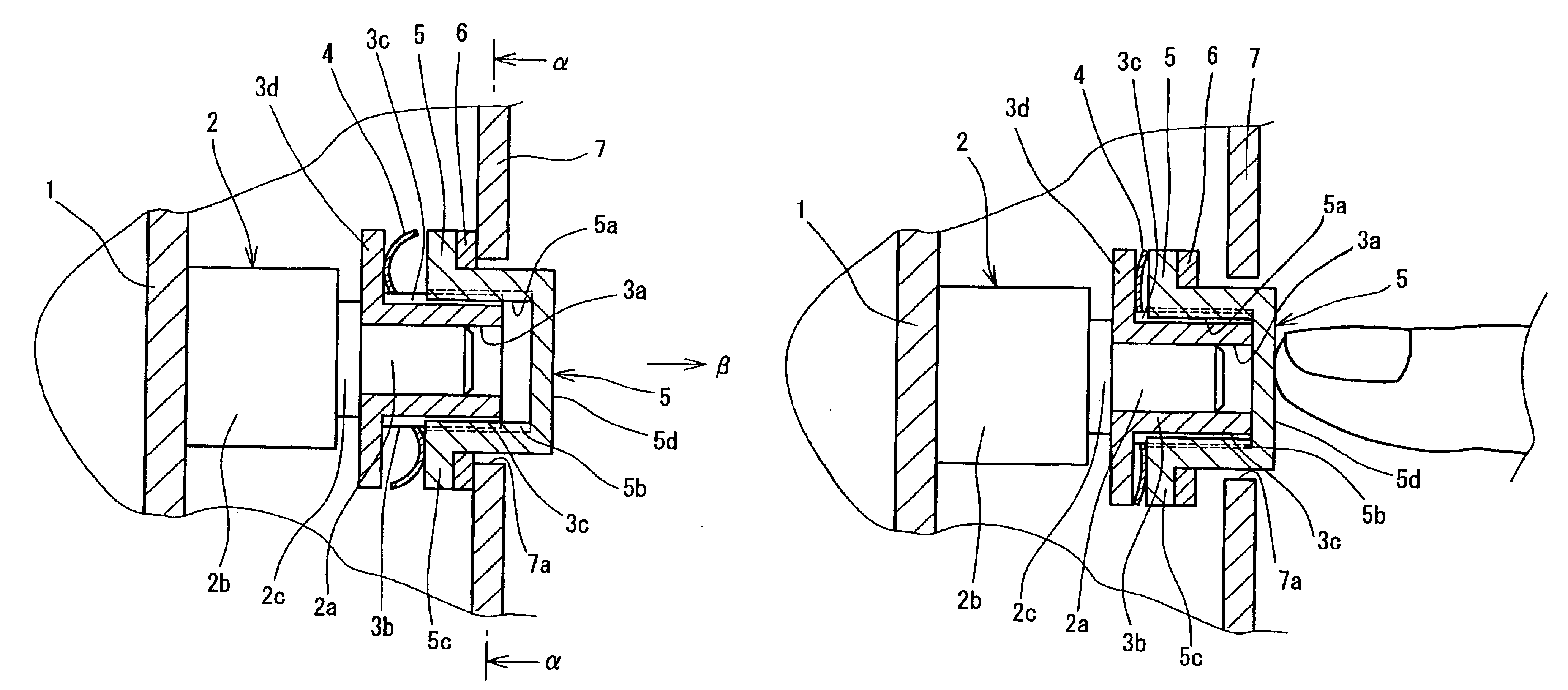
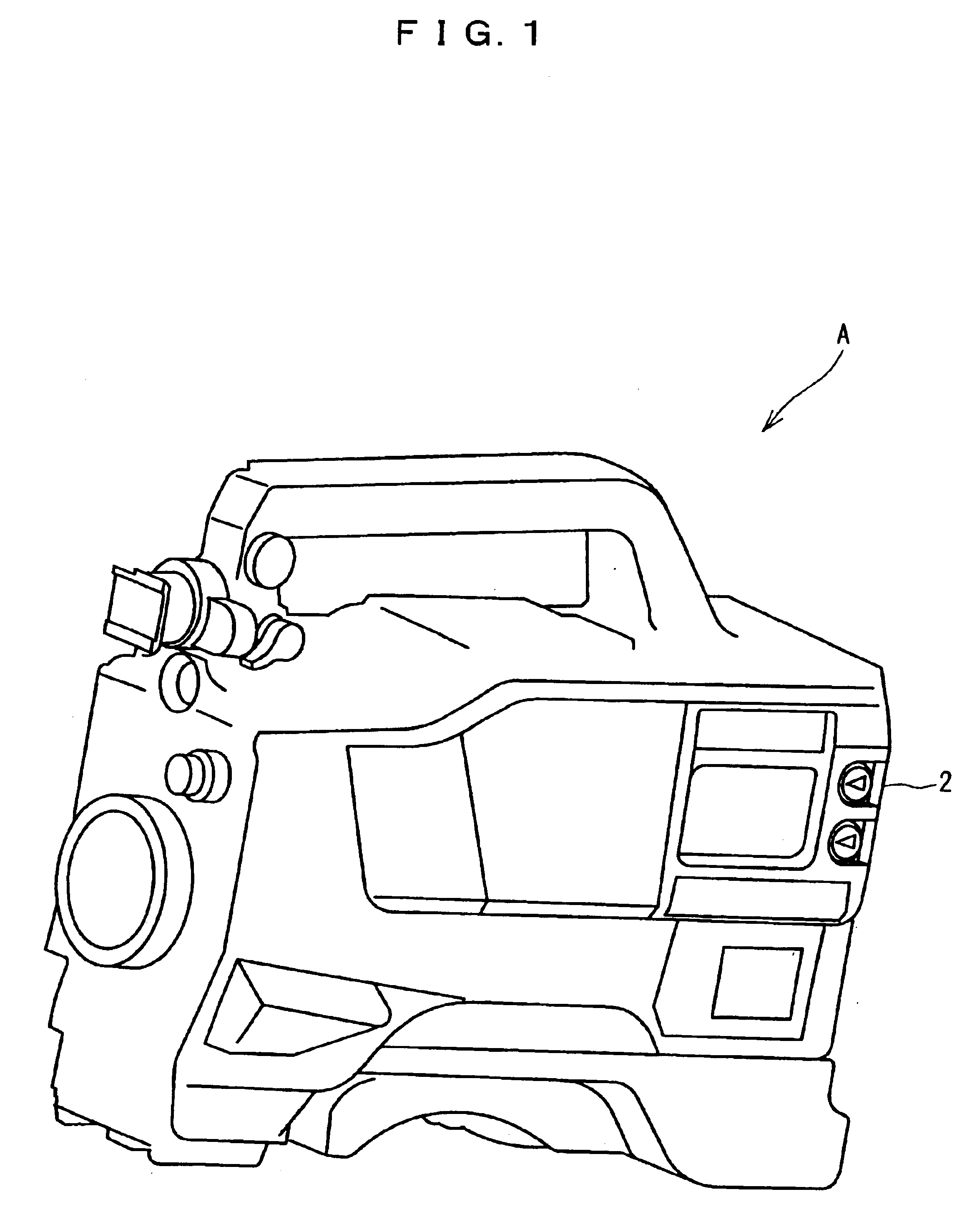
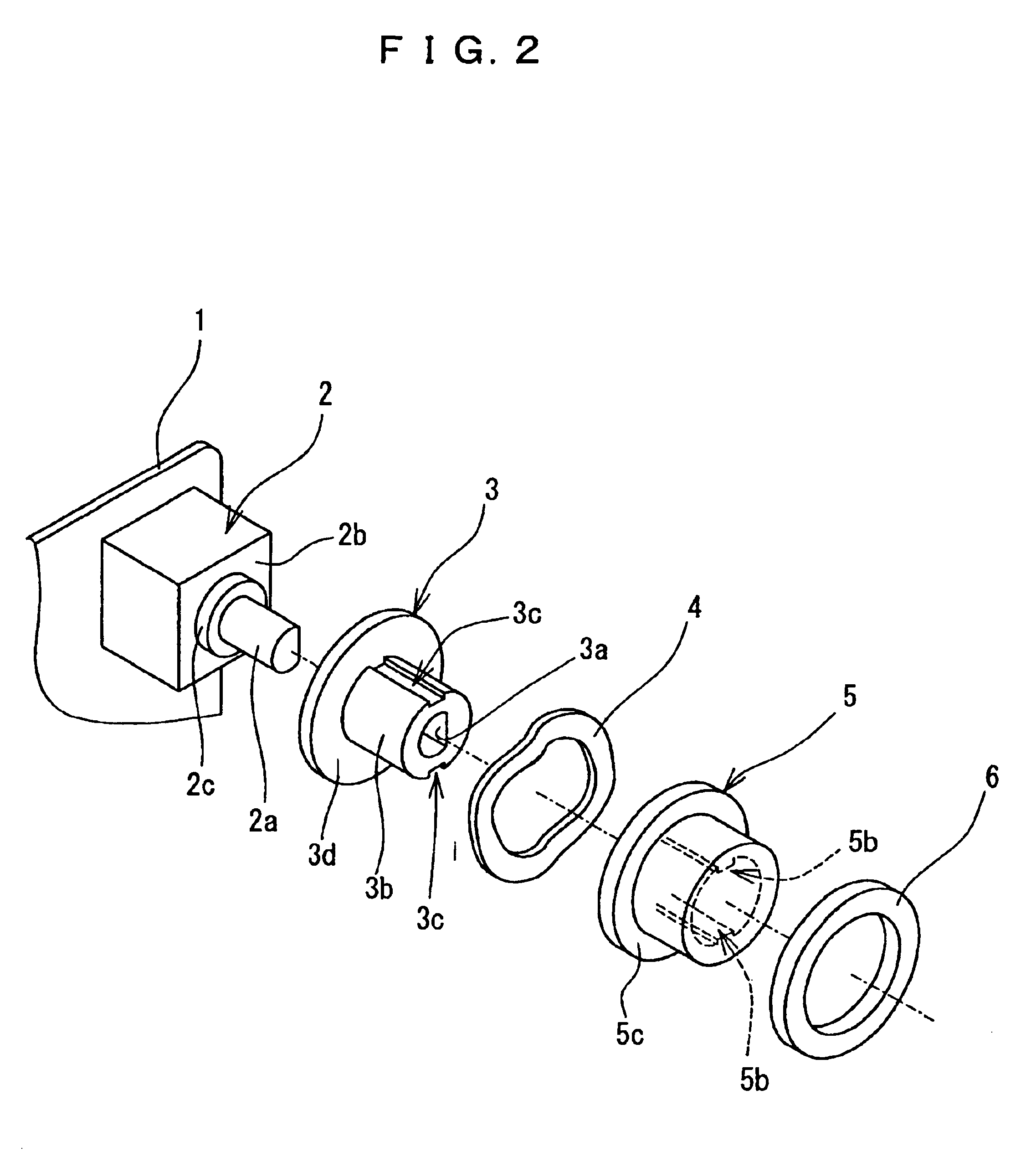
FIG. 1 is a perspective view showing a general configuration of an electronic apparatus A having a built-in anti-malfunction mechanism for a variable output device according a first embodiment of the invention. FIG. 2 is an exploded perspective view showing the structure of an anti-malfunction mechanism for a variable output device according to the first embodiment of the invention. FIG. 3 is a sectional view showing the state in which a malfunction is prevented by the anti-malfunction mechanism for the variable output device according to the first embodiment. FIG. 4 is a sectional view taken along line α—α in FIG. 3. FIG. 5 is a sectional view showing the state in which the anti-malfunction mechanism for the variable output device according to the first embodiment is in operation.

The electronic apparatus A according to this embodiment is a single-unit video camera recorder. The electronic apparatus A includes a variable output device 2 for adjusting the voice level at the time of v...

second embodiment

FIG. 6 is an exploded perspective view showing a structure of an anti-malfunction mechanism for a variable output device according to a second preferred embodiment of the invention. FIG. 7 is a sectional view showing a state in which the anti-malfunction mechanism for the variable output device according to the second embodiment shown in FIG. 7 works to prevent a malfunction.

The second embodiment basically has a similar configuration to the first embodiment. Therefore, in the second embodiment, those component parts similar or identical to the corresponding component parts of the first embodiment are designated by the same reference numerals.

Each variable output device 2 has an operating shaft 2a. The operating shaft 2a is projected out of the case 2b of the variable output device 2. Each operating shaft 2a is projected along the direction perpendicular to the surface of the circuit board 1. The operating shaft 2a has the flange 2c. The flange 2c is arranged in the vicinity of the s...


PUM


Abstract

A variable output device is mounted on a mounting unit with the operating shaft displaceable. An operating unit for transmitting the operation of the user to the operating shaft is mounted on the operating shaft relatively movably along the direction of the axis of the operating shaft, on the one hand, and in an operatively interlocked fashion along the direction of displacement of the operating shaft, on the other hand. A holding member is arranged in opposed relation with the mounting unit with the variable output device interposed therebetween. An elasticity applier urges the operating unit away from the variable output device. The holding member is provided with an operating hole. The holding member is arranged at a position in opposed relation with the mounting unit with the variable output device and the operating unit interposed therebetween. The operating unit elastically urged by the elasticity applier is brought into contact with the peripheral edge portion of the operating hole of the holding member in opposed relation with the operating hole.

Description

BACKGROUND OF THE INVENTION1. Field of the InventionThe present invention relates to a mechanism for preventing the malfunction of a variable output device built in various electronic apparatuses.2. Description of the Related ArtConventional electric apparatuses are available which comprise a variable output device such as a variable resistor and an operating unit therefor. The operating unit is a knob for manipulating and therefore adjusting the variable output device from outside the apparatus.FIG. 10 shows a mounting structure of a conventional operating unit 5. A variable output device 2 is connected by solder to a circuit board 1. The variable output device 2 has an operating shaft. The operating unit 5 is fitted on the operating shaft of the variable output device 2 to rotate integrally with the operating shaft. A part of the operating unit 5 is projected out of the electronic apparatus by way of a hole formed in an exterior case 7 of the electronic apparatus. The user adjusts...

Claims


Application Information

Patent Timeline
Patent Type & Authority Patents(United States)
IPC IPC(8): H01H3/02H01H3/20H01H19/06H01H19/10H01H19/00
CPCH01H3/20H01H19/10H01H19/06
Inventor AMANO, FUTOSHIKOUCHI, TAKAMITSUKOBAYASHI, HISAO
Owner PANASONIC CORP
Learn More