
Intravascular flow modifier and reinforcement device

a technology of which is applied in the field of intravascular flow modifier and reinforcement device, and achieves the effect of small diameter

Inactive Publication Date: 2005-04-12
MICRUS CORP
View PDF8 Cites 118 Cited by
  • Summary
  • Abstract
  • Description
  • Claims
  • Application Information

AI Technical Summary

Benefits of technology

Another advantage of the present invention is that it may be used in arteries up to renal size while still providing the benefits of placement without the use of balloons or mechanical expansions. One significant benefit in such an application is that the flow through the vessel is never fully occluded by the placement of the device of the invention, and it is possible to place the device from a free flow micro-catheter that is relatively small in diameter compared to the inside diameter of the blood vessel being treated.
is that it may be used in arteries up to renal size while still providing the benefits of placement without the use of balloons or mechanical expansions. One significant benefit in such an application is that the flow through the vessel is never fully occluded by the placement of the device of the invention, and it is possible to place the device from a free flow micro-catheter that is relatively small in diameter compared to the inside diameter of the blood vessel being treated.

Problems solved by technology

The presence of the longitudinal portion of the coil dramatically improves the pushability of the device, thereby enhancing the ability to deploy and place the device within the vasculature, an issue of considerable importance if neither balloon nor mechanical placement methods are to be used.

Method used


Image

  • Intravascular flow modifier and reinforcement device
  • Intravascular flow modifier and reinforcement device
  • Intravascular flow modifier and reinforcement device

Examples


Embodiment Construction

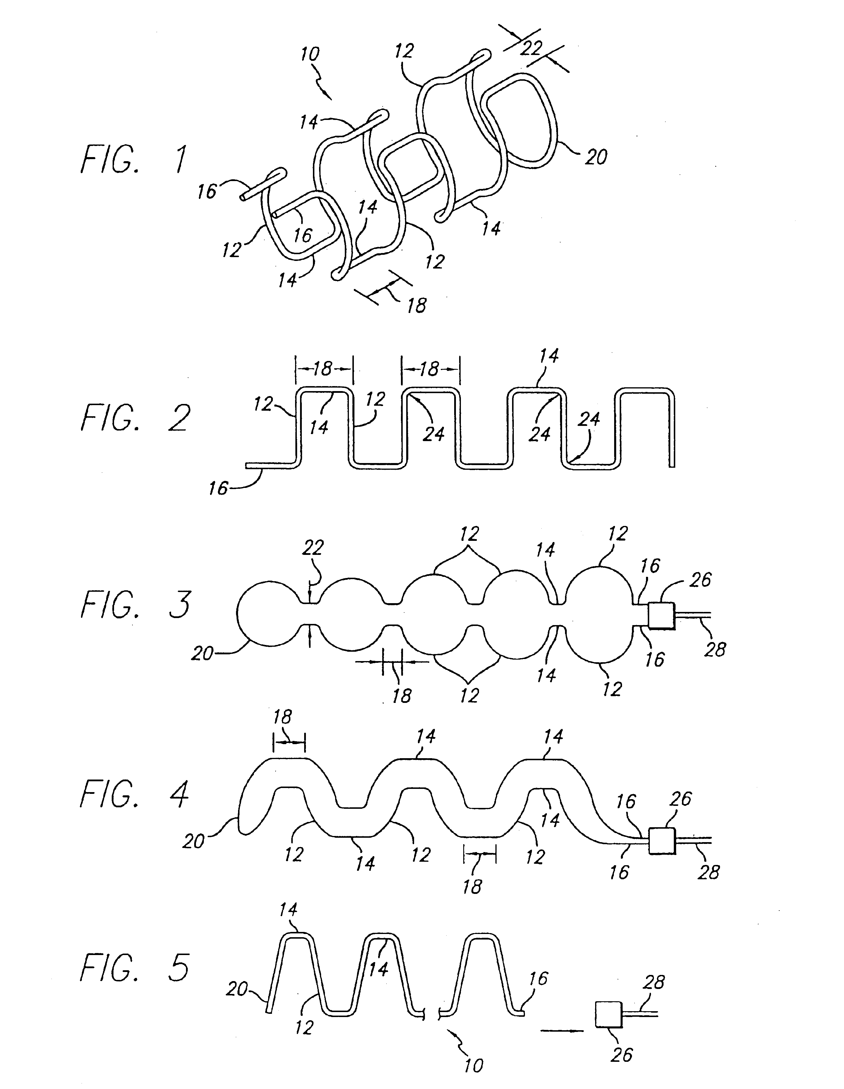
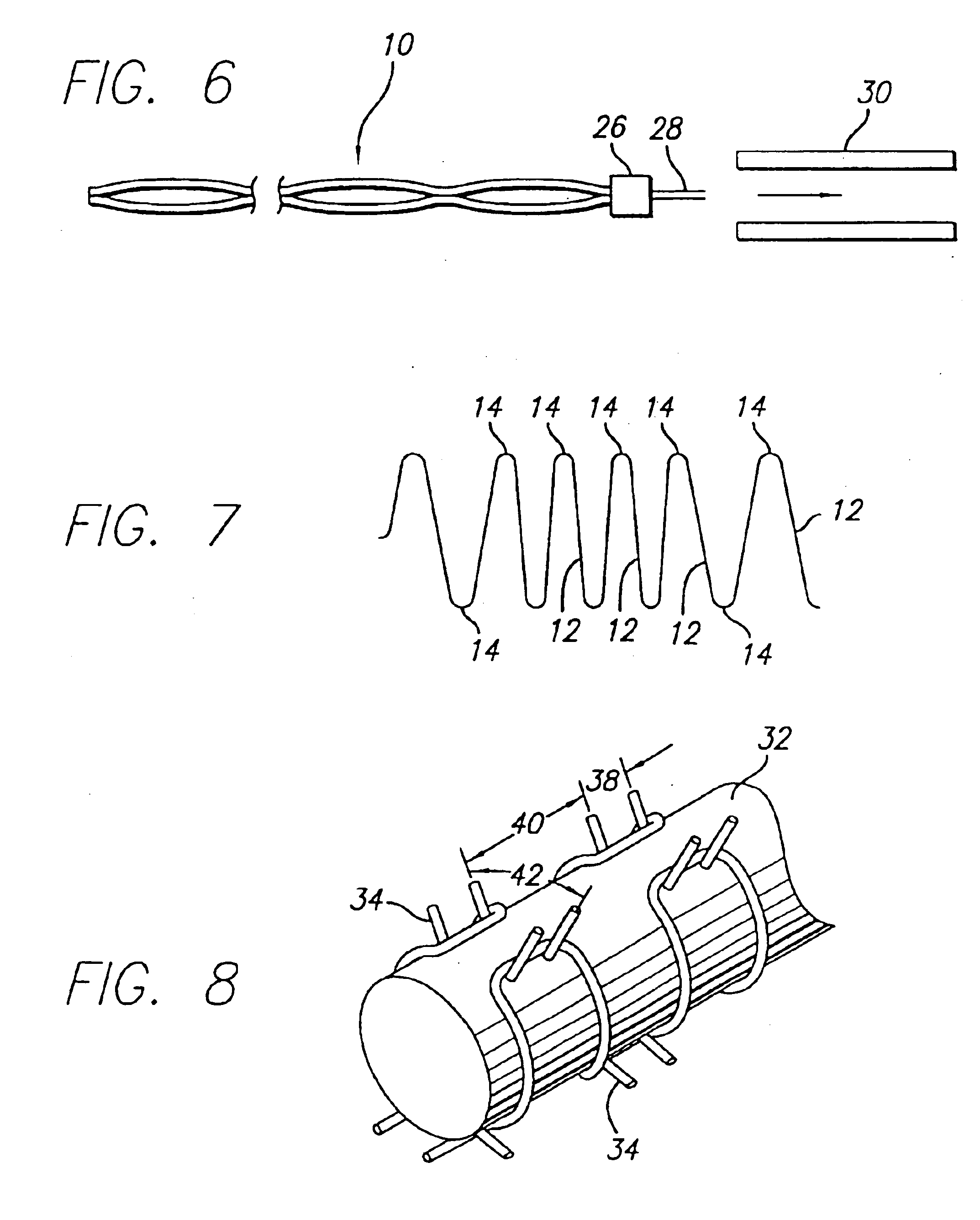
As shown in the exemplary drawings, which are provided for the purposes of illustration and not by way of limitation, the device of the present invention is designed to be deployed intravascularly without the necessity of balloons or other expansive elements and can be deployed from a micro-catheter directly into the area to be treated. The intravascular device of the present invention is particularly useful for treatment of damaged arteries incorporating aneurysms and the like, particularly those which are treatable by the use of embolic coils or other embolic devices or agents used to occlude the aneurysm. More particularly, the device of the invention is particularly well adapted to use with the types of catheters used to place such embolic coils in aneurysms, and the device may be used to reinforce the area in the vicinity of the aneurysm while allowing placement of one or more embolic coils through the gaps in the stent, while assisting in the retention of the embolic devices w...


PUM

PropertyMeasurementUnit
surface areaaaaaaaaaaa
diameteraaaaaaaaaa
resilientaaaaaaaaaa

Abstract

An intravascular flow modifier and vascular reinforcement for treatment of aneurysms is formed of one or more loops of wire of resilient material formed into a series of transverse loops and longitudinal connecting sections to configure an essentially cylindrical reinforcement device that still allows, if desired, access to the neck of an aneurysm for insertion of embolic coils and the like. The proximal and distal regions of the sinusoidal loops may be more tightly coiled than the intermediate regions of the loops, or may have a larger diameter than the intermediate regions. The intravascular flow modifier and vascular reinforcement device can be provided with an outer covering that can be formed as a fiber, and can be woven, or can be formed as a ribbon wound about the intravascular flow modifier and vascular reinforcement device. The wire of resilient material can also be coated with a hydrophilic material. One or more round or oval intermediate loops extending radially outward may also be provided. An apparatus for removing clots may also be formed from one or more loops of wire of resilient material in a hollow conical shape non-detachably joined to a deployment device, to trap and hold clots within a vessel.

Description

BACKGROUND OF THE INVENTION1. Field of the InventionThe present invention relates to an intravascular flow modifier and reinforcement device for use within a body vessel, and more particularly, for a device to be used in combination with vasoocclusive devices placed in an aneurysm for the purpose of occluding an aneurysm, whereby the invention provides reinforcement for the area of the blood vessel in the vicinity of the aneurysm.2. Description of the Related ArtThe progress of the medical arts related to treatment of vascular malformations has dramatically improved with the availability of intravascular devices capable of operating entirely within the vasculature. Thus, many highly invasive surgical procedures and inoperable conditions have been treated by the use of an expanding number of devices and procedures designed for those purposes. One particularly useful development in the medical arts has been the ability to treat defects in relatively small arteries and veins, such as t...

Claims


Application Information

Patent Timeline
Patent Type & Authority Patents(United States)
IPC IPC(8): A61F2/06A61F2/01A61B17/12A61F2/00A61B17/00A61B17/22A61F2/88A61F2/90A61L27/00A61L31/00
CPCA61B17/12118A61B17/1219A61F2/01A61F2/88A61F2/885A61F2/90B21F45/008A61B17/12172A61F2230/0071A61F2/07A61F2002/072A61F2210/0014A61F2250/0036A61F2250/0037A61B17/12022A61F2002/016A61F2230/0013A61F2230/0091A61F2/012
Inventor DENARDO, ANDREW J.FERRERA, DAVID A.WILSON, PETERLEI, LOK A.
Owner MICRUS CORP
Learn More