
Split wheel stump cutter with replaceable tooth blocks and cutting teeth

a stump cutter and replacement technology, applied in the field of cutting wheels, can solve the problems of considerable wear and breakage of the tooth block, and the peripheral surface of the cutting wheel is also subject to considerable wear and breakag

Inactive Publication Date: 2005-04-12
BENNINGTON JOHN W
View PDF10 Cites 40 Cited by
  • Summary
  • Abstract
  • Description
  • Claims
  • Application Information

AI Technical Summary

Problems solved by technology

Because of these hidden obstacles, the teeth are subject to considerable wear and breakage, and the peripheral surface of the cutting wheel experiences considerable wear as well.

Method used


Image

  • Split wheel stump cutter with replaceable tooth blocks and cutting teeth
  • Split wheel stump cutter with replaceable tooth blocks and cutting teeth
  • Split wheel stump cutter with replaceable tooth blocks and cutting teeth

Examples


Embodiment Construction

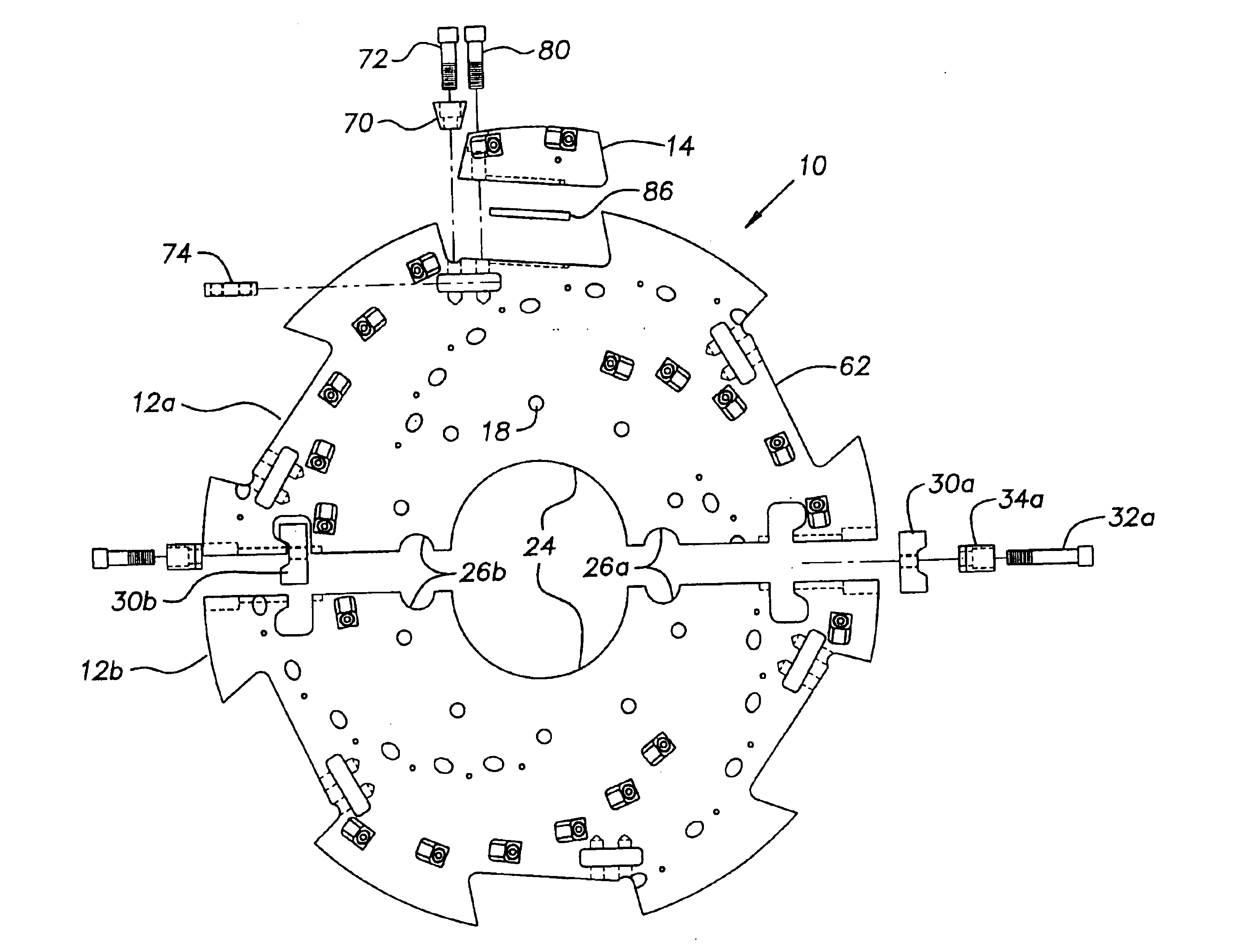
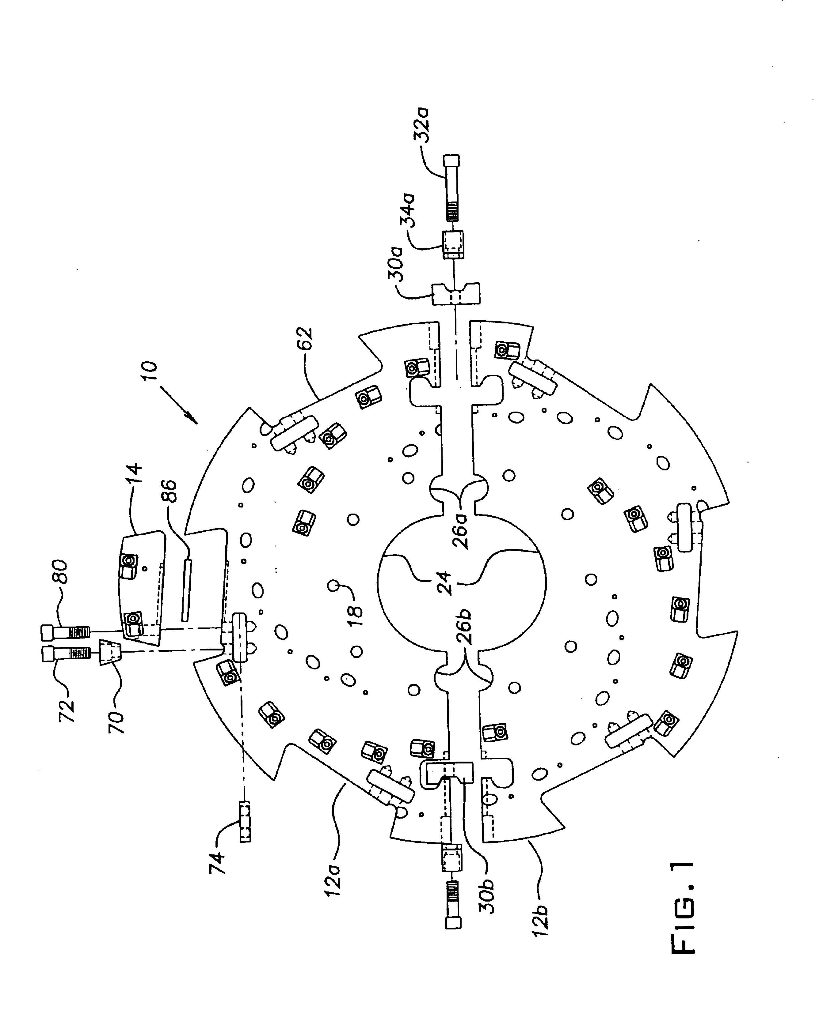
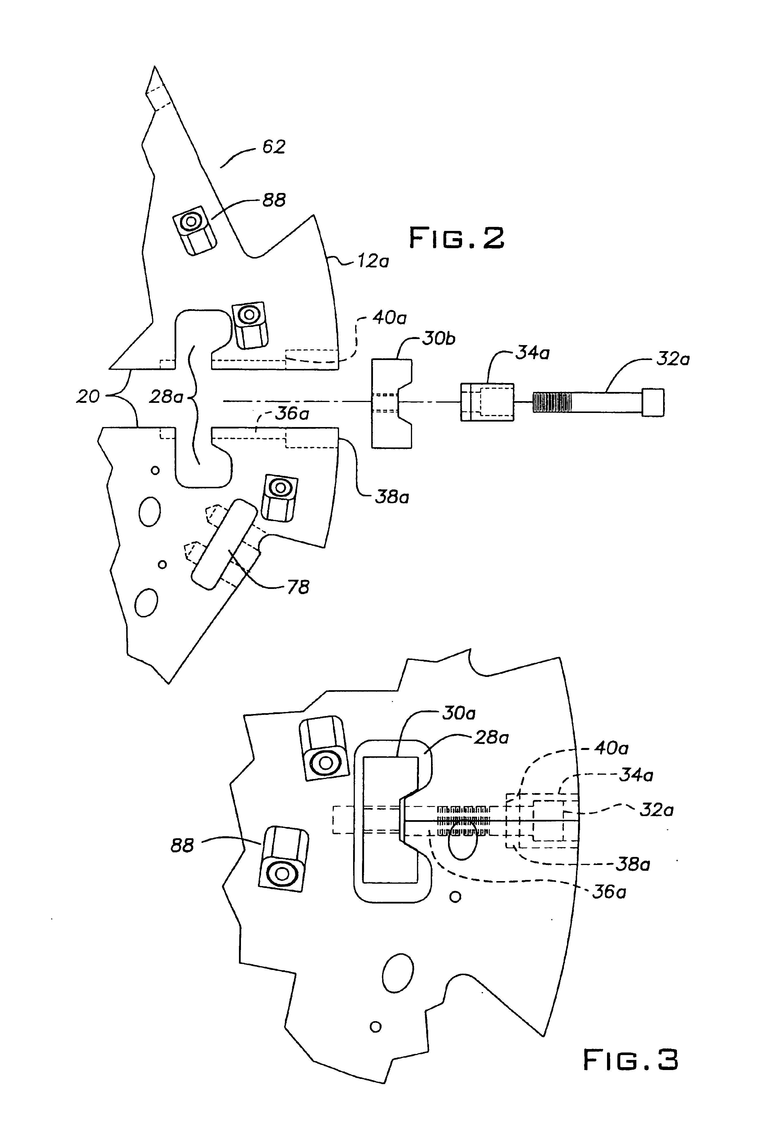
The grinding wheel of the present invention is fabricated in two halves that are adapted to be held together by a butterfly type clamp. The halves are aligned in place by a wheel key which is held tight by a bolt going through the middle of the wheel key and the wheel, to the butterfly wheel clamp.

The grinding wheel also has removable wheel sections called blocks. These blocks are held in place in four ways. One, the wheel is machined with a cut-out specifically designed for the blocks to set into them. The wheel receives the block with the back and bottom face of the block fitting into it. The space between the front face of the block and the wheel is designed for a wedge to set into it. Two, a safety bolt goes through the block to a common nut plate or a nut in the wheel. Three, a wedge is set in between the wheel and front face of the block which is held in place by a bolt that goes through the wedge and into the common nut plate or nut in the wheel. Fourth, a key and keyway slip...


PUM


Abstract

A stump grinding apparatus having a split cutting wheel includes several replaceable cutter blocks secured to the periphery of the wheel. One or more replacement teeth are removably anchored in holes in each block and may also be mounted on holes in the side of the split wheel as well. The teeth are typically provided with a hardened cutting face, and are reinforced with an extension projecting back from the face. Each tooth includes a shank which fits into one of the holes. The shank contains a groove which receives a spring clip or a spring pin for securing the tooth in the hole. The wheel periphery contains individual recesses that are shaped to receive the cutter blocks. Each block includes means for insuring alignment of the block in the corresponding recess. The block is wedged tightly into its recess to reduce the likelihood of accidental removal.

Description

BACKGROUND OF THE INVENTION1. Field of the InventionThis invention relates to the field of cutting wheels useful for grinding tree stumps. More specifically, it relates to a stump cutter assembly and the component parts thereof.2. Description of the Related ArtIt is known to provide a stump grinding apparatus to cut and dispose of tree stumps. The device finds use for agricultural applications, for proper lawn maintenance and care, and for site development. It is often required to lower a protruding stump to a level that is below grade so that it will not interfere with plowing, disking and other farm tasks. For pleasing appearance of residential lawns, stumps of dead and fallen trees must likewise be cut away to a point that is below grade to allow for soil to be placed thereover for seeding or planting. When used for site development, the apparatus permits soil to be moved as needed.Typically, such a device includes a rotatable grinding wheel having a plurality of cutting teeth di...

Claims


Application Information

Patent Timeline
Patent Type & Authority Patents(United States)
IPC IPC(8): A01G23/00A01G23/06
CPCA01G23/067
Inventor BENNINGTON, JOHN T.
Owner BENNINGTON JOHN W
Learn More