
Method for correcting measurement error, method of determining quality of electronic component, and device for measuring characteristic of electronic component

a technology of measurement error and measurement method, applied in the direction of measurement device, resistance/reactance/impedence, instruments, etc., can solve the problems of different measurement errors based on the used measuring device, inability to meet conditions, and significant differences between measurement errors generated by different measuring devices

Inactive Publication Date: 2005-04-05
MURATA MFG CO LTD
View PDF4 Cites 10 Cited by
  • Summary
  • Abstract
  • Description
  • Claims
  • Application Information

AI Technical Summary

Benefits of technology

Accordingly, it is a main object of the present invention to provide a correction method for precisely correcting a measured impedance in a high-frequency band of 1 MHz to several GHz.
In order to achieve the above-described object, the present invention provides a method of correcting a measurement error, in which the impedance of an electronic component is measured by an actual measuring device generating a measurement result different from that of a standard measuring device, and then the obtained value of impedance is corrected to the value which would be obtained from the standard measuring device. The method includes preparing in advance a correction-data obtaining sample which generates an impedance equal to an arbitrary impedance of the electronic component by a measuring operation; measuring the impedance of the correction-data obtaining sample by using the standard measuring device and the actual measuring device; obtaining an interrelated expression of the measurement result generated by the actual measuring device and the measurement result generated by the standard measuring device, the interrelated expression uniquely indicating the relationship between the true measurement value of the standard measuring device and the true measurement of the actual device; and correcting the impedance of the electronic component to the impedance which will be obtained from the standard measuring device by substituting the impedance of the electronic component measured by the actual measuring device into the interrelated expression so as to calculate the interrelated expression. Accordingly, the following effects can be obtained.
In this configuration, the interrelated expression of the actual and standard measuring devices is obtained based on the measurement result of the correction-data obtaining sample in which the impedance is not identified. Also, based on this interrelated expression, the impedance of the electronic component is corrected to the impedance which would be obtained from the standard measuring device. Accordingly, calibration using an expensive standard device is not necessary, and the actual measuring jig included in the actual measuring device need not be adjusted. Further, since the electronic characteristic is corrected by theoretical calculation, reproducibility of impedance can be enhanced regardless of the shape (coaxial / non-coaxial) of the electronic component.
In this determining method, the impedance of the electronic component measured by the actual measuring device is corrected by using the method of correcting a measurement error of the present invention so as to determine the quality of the electronic component by comparing the corrected impedance and the required impedance. Accordingly, the quality of the electronic component can be determined with great precision.
Also, the present invention provides a device for measuring the characteristic of an electronic component, which can perform the above-described method of correcting a measurement error.

Problems solved by technology

In this case, a different measurement error occurs depending on the used measuring device.
When impedance in a low-frequency band is measured, the measurement error is relatively insignificant, which leads to only a small problem.
However, when impedance in a high-frequency band of 1 MHz to 2 GHz is measured, the difference between measurement errors generated by different measuring devices is significant.
However, these conditions cannot be satisfied for the following reason.
That is, the ideal open / short states of the jig cannot be realized practically, and thus the first condition cannot be satisfied.
However, even if these instructions are faithfully followed, it is impossible to realize true open / short states, and thus correction cannot be performed with great precision.
Of course, the open / short / load correction method has the same disadvantage as that of the open / short correction method.
Furthermore, in the open / short / load correction method, a calibration value of the device used for load correction cannot be measured precisely.
However, in the above-described correction methods, a correction precision required for such a guarantee of impedance in a high-frequency band cannot be obtained.
Accordingly, it is practically impossible to realize a high-precision correction in a high-frequency band of 1 MHz to several GHz by using the open / short / load correction method, as long as an extremely precise standard device cannot be obtained.
However, such a standard device can be fabricated only in an electronic component having a shape which can be attached to a coaxial connector.
It is practically impossible to fabricate such a standard device in general electronic components, such as chip capacitors and chip coils.

Method used


Image

  • Method for correcting measurement error, method of determining quality of electronic component, and device for measuring characteristic of electronic component
  • Method for correcting measurement error, method of determining quality of electronic component, and device for measuring characteristic of electronic component
  • Method for correcting measurement error, method of determining quality of electronic component, and device for measuring characteristic of electronic component

Examples


Embodiment Construction

)

Hereinafter, an embodiment of the present invention will be described with reference to the drawings. In the embodiment, the present invention is embodied in a method of correcting a measurement error, which occurs when the impedance of an electronic component, such as a surface-mount chip coil, is measured by a measuring device including an impedance analyzer.

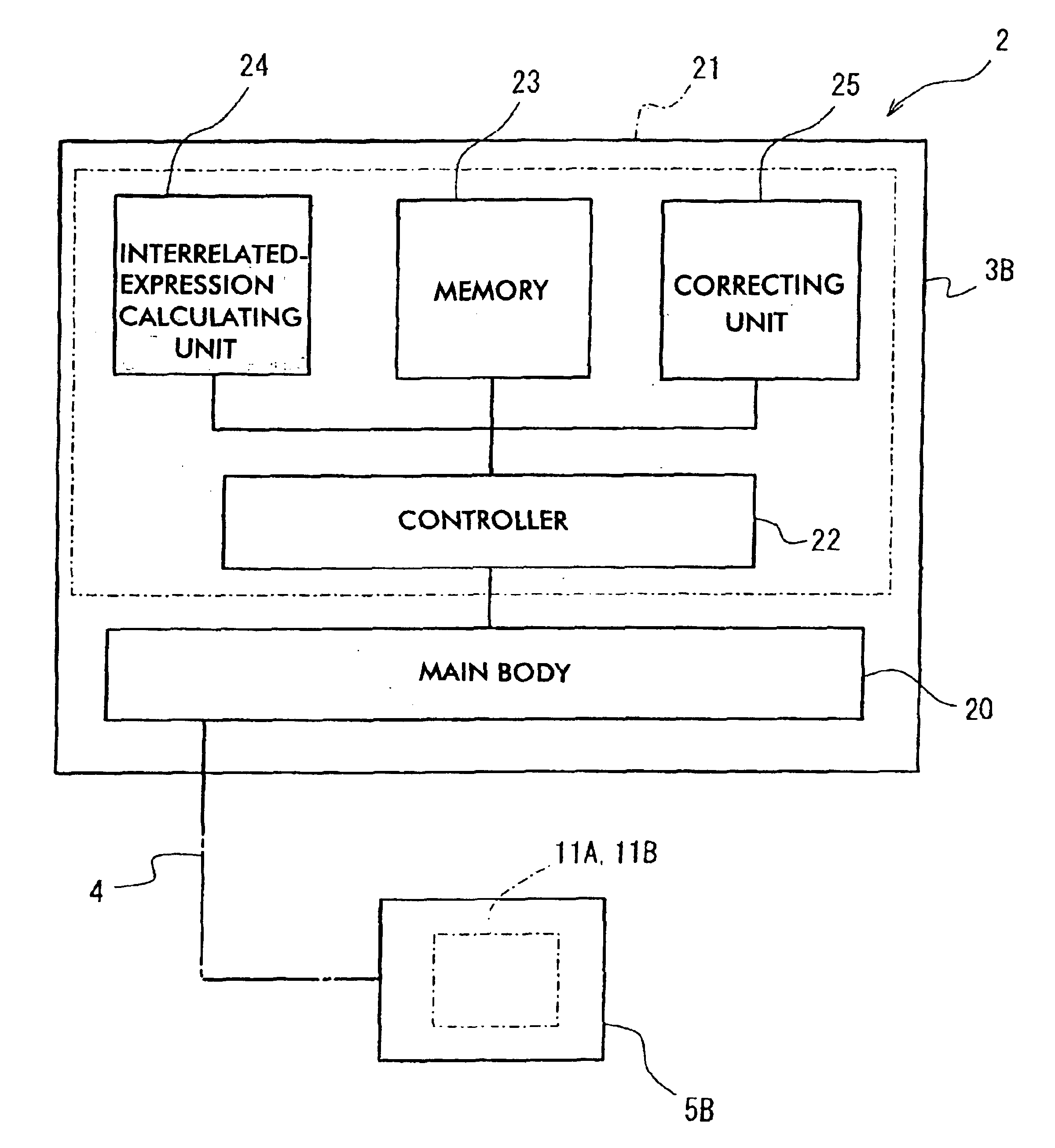
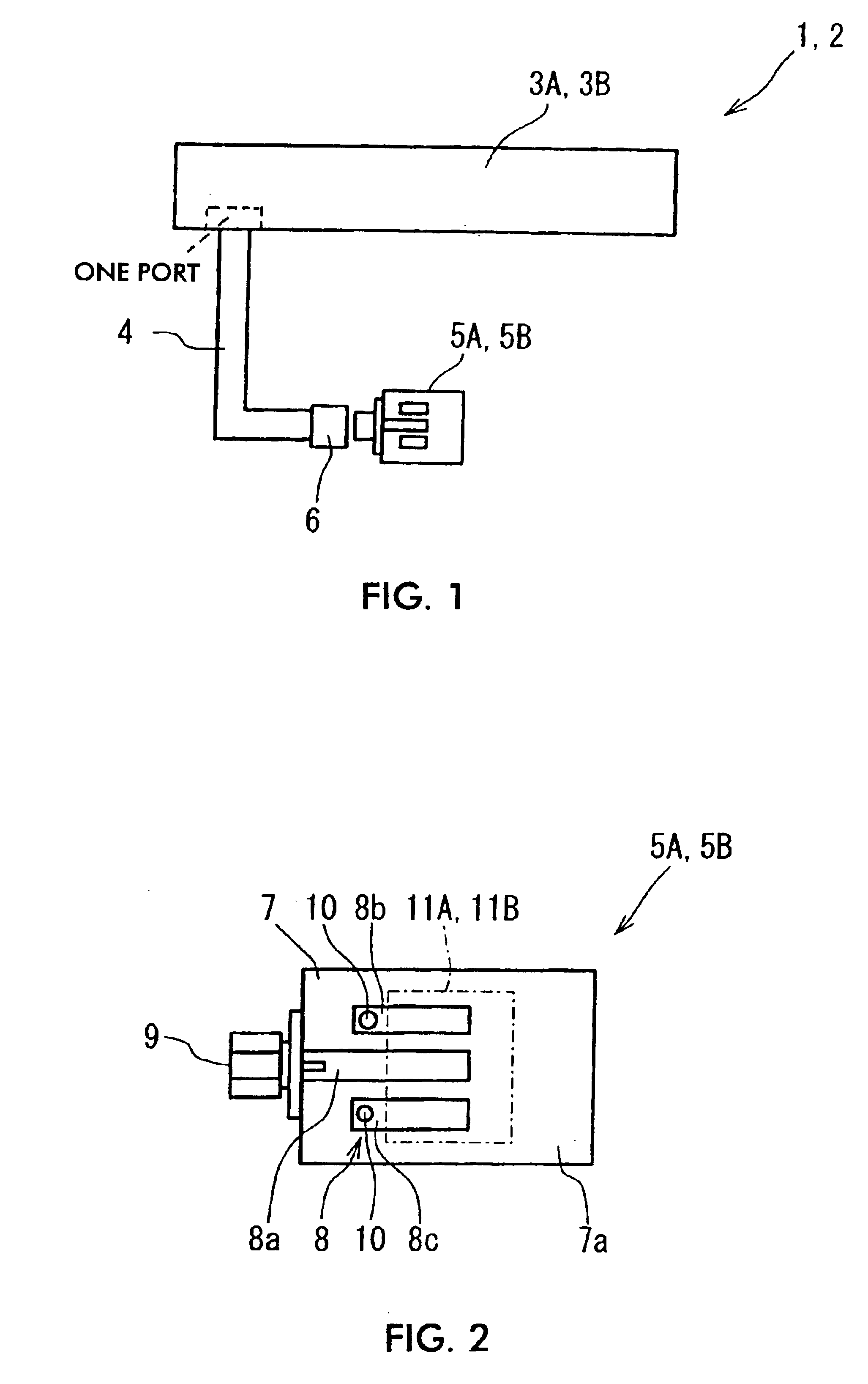
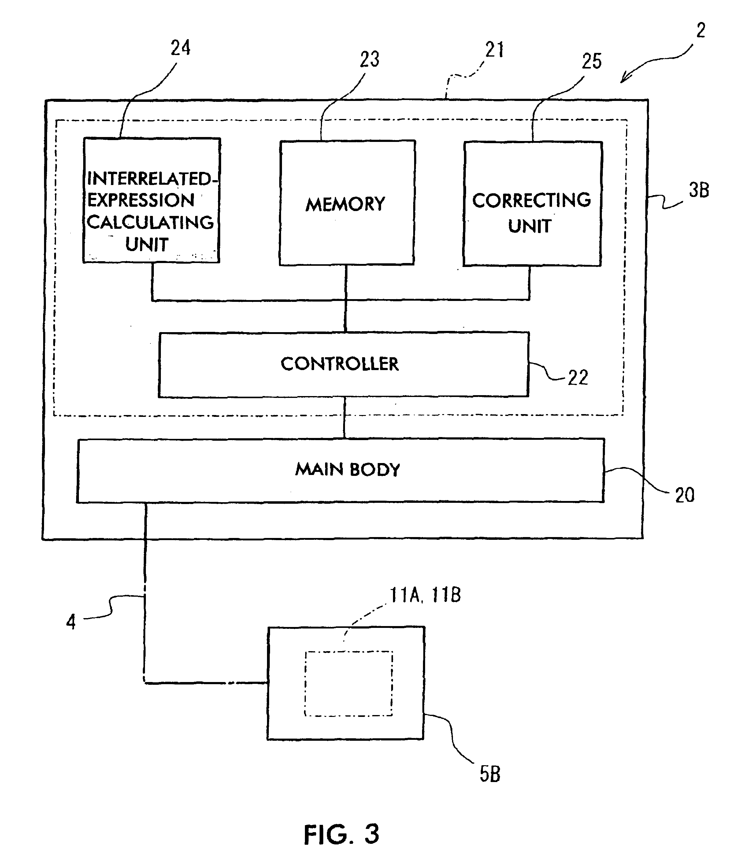
FIG. 1 is a plan view showing the configuration of a measuring device of the embodiment; FIG. 2 is a plan view showing the configuration of a measuring jig; FIG. 3 is a block diagram showing an impedance analyzer included in the measuring device; FIG. 4 is a back-side view showing the configuration of a sample to be measured (electronic component or correction-data obtaining sample); and FIG. 5 is a plan view showing the configuration of the correction-data obtaining sample.

As shown in FIG. 1, a standard measuring device 1 and an actual measuring device 2 include impedance analyzers 3A and 3B, coaxial cables 4, and measuring ...


PUM


Abstract

The impedance of a correction-data obtaining sample is measured by a standard measuring device and an actual measuring device so as to obtain an interrelated expression of the measurement results generated by the standard and actual measuring devices. The impedance of an electronic component measured by the actual measuring device is substituted into the interrelated expression and the expression is calculated. Accordingly, the impedance of the electronic component is corrected to the impedance which would be obtained from the standard measuring device.

Description

BACKGROUND OF THE INVENTION1. Field of the InventionThe present invention relates to a method of correcting a measurement error, in which the impedance of an electronic component measured by an actual measuring device is corrected to the impedance which will be obtained when measurement is performed by using a standard measuring device. Also, the present invention relates to a method of determining the quality of an electronic component using the correction method, and a device for measuring the characteristic of an electronic component for performing the correction method.2. Description of the Related ArtThe impedance of an electronic component or the same type of electronic components may be measured by a plurality of measuring devices, for example, a measuring device of the manufacturer of the electronic component and that of a user.In this case, a different measurement error occurs depending on the used measuring device. Therefore, the reproducibility of the measurement value is...

Claims


Application Information

Patent Timeline
Patent Type & Authority Patents(United States)
IPC IPC(8): G01R35/00
CPCG01R35/005
Inventor KAMITANI, GAKU
Owner MURATA MFG CO LTD
Learn More