
Disk drive comprising control circuitry powered by a secondary voltage supplied by a center tap of a spindle motor during a normal operating mode

Inactive Publication Date: 2005-04-05
WESTERN DIGITAL TECH INC
View PDF8 Cites 110 Cited by
  • Summary
  • Abstract
  • Description
  • Claims
  • Application Information

AI Technical Summary

Benefits of technology

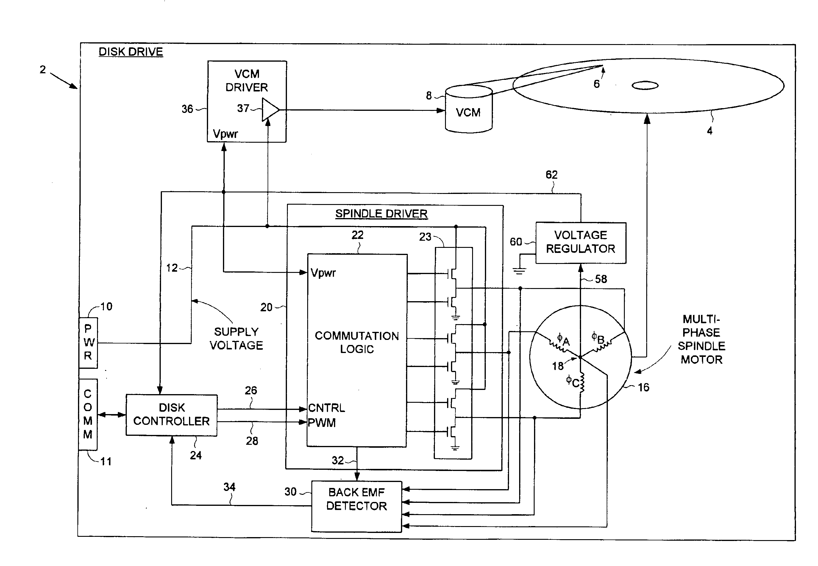
The present invention may be regarded as a disk drive comprising a disk having a plurality of tracks, a head, a voice coil motor for actuating the head radially over the disk, and an interface for receiving a supply voltage from a host computer. The disk drive further comprises a multiphase spindle motor for rotating the disk, the multi-phase spindle motor comprising a plurality of windings, each winding comprising a first end and a second end, the second ends connected together at a center tap. A spindle driver, responsive to the supply voltage, commutates the windings over commutation intervals during a normal operating mode. The disk drive further comprises control circuitry for controlling at least one operation of the disk drive. A secondary voltage is supplied by the center tap of the windings, and the control circuitry is powered by the secondary voltage during the normal operating mode.
In one embodiment, the disk drive further comprises a voltage regulator for regulating the secondary voltage used to power the control circuitry during the normal operating mode.
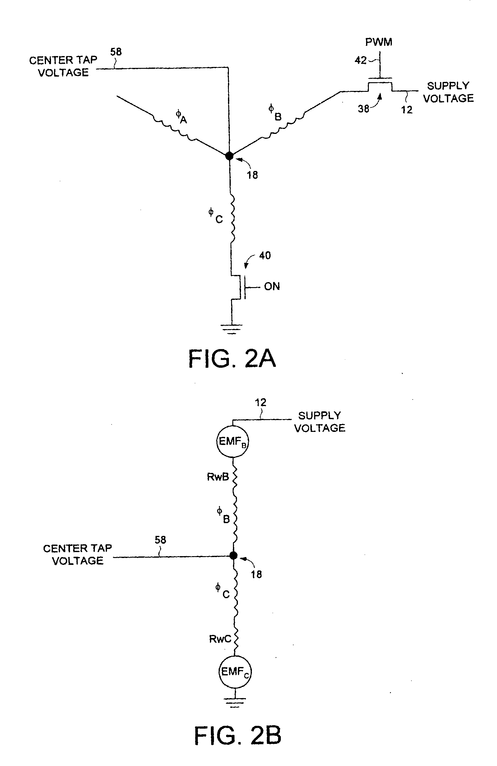
In one embodiment, the windings are wound to control the secondary voltage supplied by the center tap of the windings.
In another embodiment, the disk drive comprises a switch for connecting the center tap voltage to the voltage regulator, wherein the switch is modulated to control the secondary voltage supplied by the center tap of the windings.
In still another embodiment, the spindle driver connects the first end of a first one of the windings and the first end of a second

Problems solved by technology

Requiring the host computer to provide two supply. voltages can increase the cost of the host computer in certain applications, such as mobile devices, set top boxes, game systems, etc., which may operate on a single supply voltage.

Method used


Image

  • Disk drive comprising control circuitry powered by a secondary voltage supplied by a center tap of a spindle motor during a normal operating mode
  • Disk drive comprising control circuitry powered by a secondary voltage supplied by a center tap of a spindle motor during a normal operating mode
  • Disk drive comprising control circuitry powered by a secondary voltage supplied by a center tap of a spindle motor during a normal operating mode

Examples


Embodiment Construction

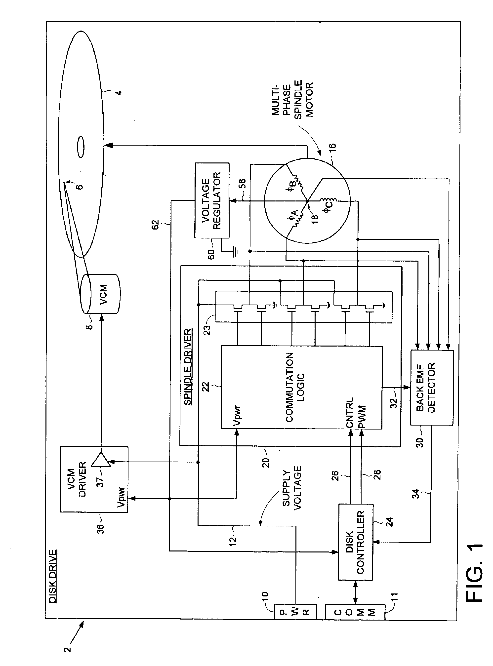
FIG. 1 shows a disk drive 2 according to an embodiment of the present invention comprising a disk 4 having a plurality of tracks, a head 6, a voice coil motor 8 for actuating the head 6 radially over the disk 4, and an interface 10 for receiving a supply voltage 12 from a host computer. The disk drive 2 further comprises a multi-phase spindle motor 16 for rotating the disk 4, the multi-phase spindle motor 16 comprising a plurality of windings (e.g., φA, φB, φC), each winding comprising a first end and a second end, the second ends connected together at a center tap 18. A spindle driver 20, responsive to the supply voltage 12, commutates the windings over commutation intervals during a normal operating mode of the disk drive 2. The disk drive 2 further comprises control circuitry (e.g., a disk controller 24) for controlling at least one operation of the disk drive 2. A secondary voltage 58 is supplied by the center tap 18 of the windings, and the control circuitry is powered by the s...


PUM


Abstract

A disk drive is disclosed comprising an interface for receiving a supply voltage from a host computer and control circuitry for controlling at least one operation of the disk drive. The supply voltage is applied to the windings of a multi-phase spindle motor in a commutation sequence during a normal operating mode, and a secondary voltage supplied by a center tap of the windings is used to power the control circuitry during the normal operating mode.

Description

BACKGROUND OF THE INVENTION1. Field of the InventionThe present invention relates to disk drives for computer systems. More particularly, the present invention relates to a disk drive comprising control circuitry powered by a secondary voltage supplied by a center tap of a spindle motor during a normal operating mode.2. Description of the Prior ArtDisk drives typically employ a multi-phase spindle motor (e.g., a three phase spindle motor) for spinning a disk while a head writes data to and reads data from the disk. The head is connected to a distal end of an actuator arm which is rotated about a pivot by a voice coil motor (VCM) in order to actuate the head radially over the disk to access radially spaced, concentric tracks. The disk drive receives power from a host computer, including a 12V supply for powering the spindle motor and VCM, and a 5V supply for powering the control circuitry for controlling the operation of the disk drive. Requiring the host computer to provide two supp...

Claims


Application Information

Patent Timeline
IPC IPC(8): G11B15/46G11B25/04G11B33/12
CPCG11B33/122G11B25/043
Inventor PATTON, III, CHARLES R.BENNETT, GEORGE J.
Owner WESTERN DIGITAL TECH INC
Learn More