Eureka AIR delivers breakthrough ideas for toughest innovation challenges, trusted by R&D personnel around the world.

Micropumps with passive check valves

a micro-fluidic pump and check valve technology, applied in the field of micro-fluidic pumps, can solve the problems of general inability to integrate microfluidic pumps in monolithic substrates, conventional pump designs are generally not suitable for microfluidic technologies, and the application of microfluidic systems is generally too cumbersome and complex, so as to improve process control and reduce cos

Inactive Publication Date: 2005-04-05
WATERS TECH CORP
View PDF19 Cites 45 Cited by
  • Summary
  • Abstract
  • Description
  • Claims
  • Application Information

AI Technical Summary

Benefits of technology

The present invention allows for better control over processes when making integrated micro-pumps that are cheaper than previous options. This results because it provides new ways to make these pumps more efficiently and effectively.

Problems solved by technology

The technical problem addressed in this patent is the lack of effective pumps designed specifically for small scale microfluidic systems made up of monolithic ceramic material. Current pumps tend to be bulky and unreliable when trying to achieve efficient flow control without adding complexity and increasing costs. There is also no known solution for creating autonomous pumps with built-in checks valves that can operate reliably in such environments.

Method used


Image

  • Micropumps with passive check valves
  • Micropumps with passive check valves
  • Micropumps with passive check valves

Examples


Embodiment Construction

The following descriptions are of exemplary embodiments of the invention and the inventors' conceptions of the best mode and are not intended to limit the scope, applicability or configuration of the invention in any way. Rather, the following description is intended to provide convenient illustrations for implementing various embodiments of the invention. As will become apparent, changes may be made in the function and / or arrangement of any of the elements described in the disclosed exemplary embodiments without departing from the spirit and scope of the invention.

Various representative implementations of the present invention may be applied to any system and / or method for fluid transport. As used herein, the terms “fluid”, “fluidic” and / or any contextual, variational or combinative referent thereof, are generally intended to include anything that may be regarded as at least being susceptible to characterization as generally referring to a gas, a liquid, a plasma and / or any matter,...


PUM


Abstract

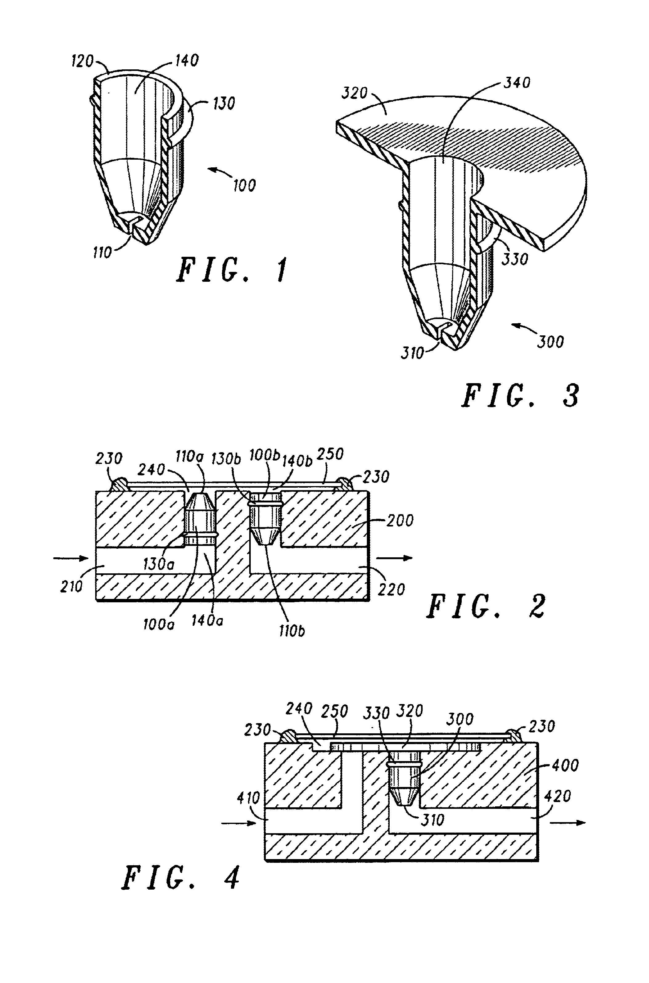
An exemplary device and method for microfluidic transport is disclosed as providing inter alia a passive check valve (100), a fluid inlet channel (210), a fluid outlet channel (220) and a pumping cavity (240). The fluid inlet channel (210) is generally configured to flow a fluid through the check valve (100). The check valve (100) generally provides substantially passive means for preventing or otherwise decreasing the incidence of purged outlet fluid re-entering either the pumping cavity (240) or the fluid inlet channel (210). Accordingly, the reduction of backflow generally tends to enhance overall pumping performance and efficiency. Disclosed features and specifications may be variously controlled, adapted or otherwise optionally modified to improve micropump operation in any microfluidic application. Exemplary embodiments of the present invention representatively provide for substantially self-priming micropumps that may be readily integrated with, for example, existing portable ceramic technologies for the improvement of device package form factors, weights and other manufacturing and/or device performance metrics.

Description


Claims


Application Information

Patent Timeline
Owner WATERS TECH CORP
Why Eureka
Eureka Blog
Learn More