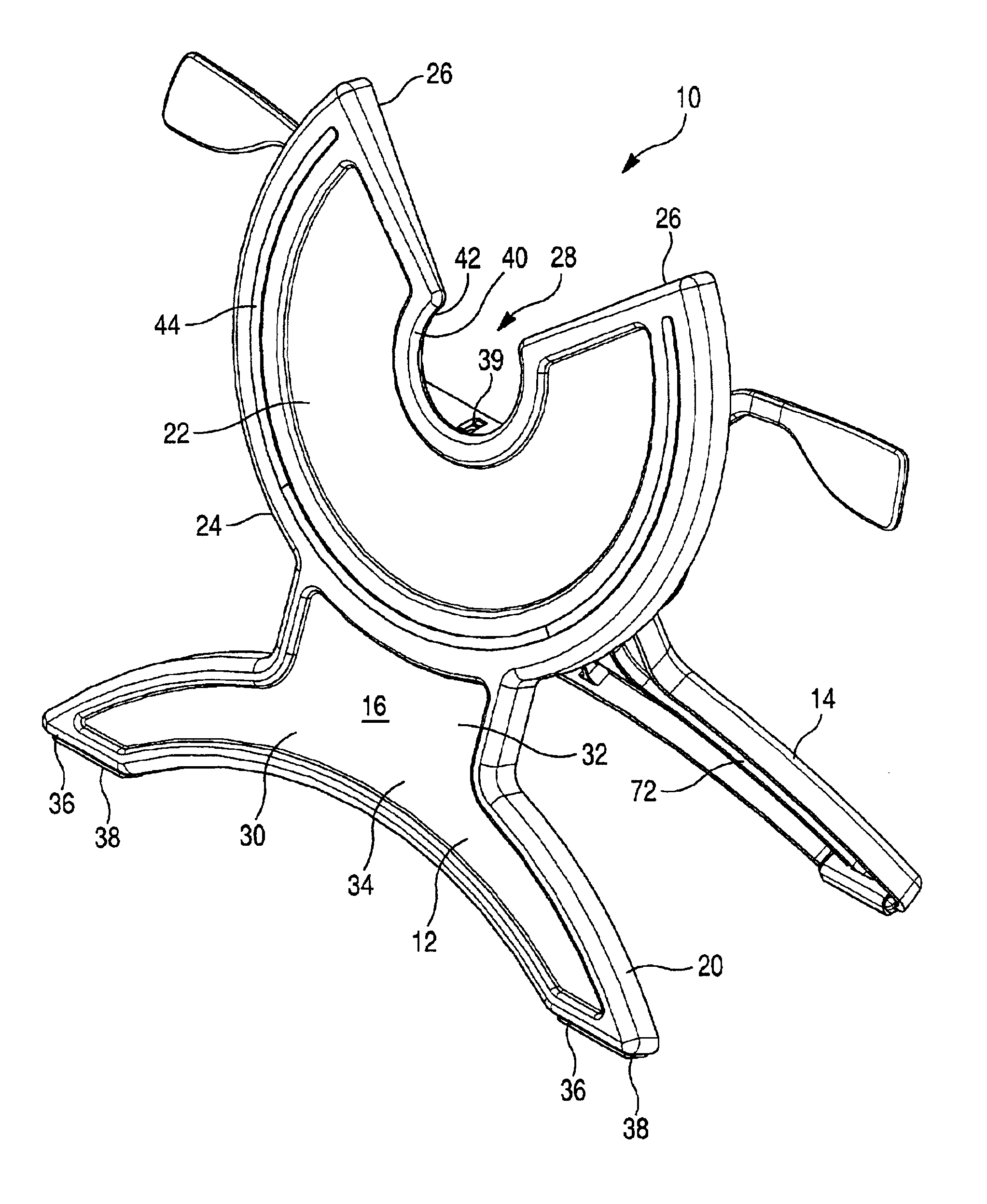
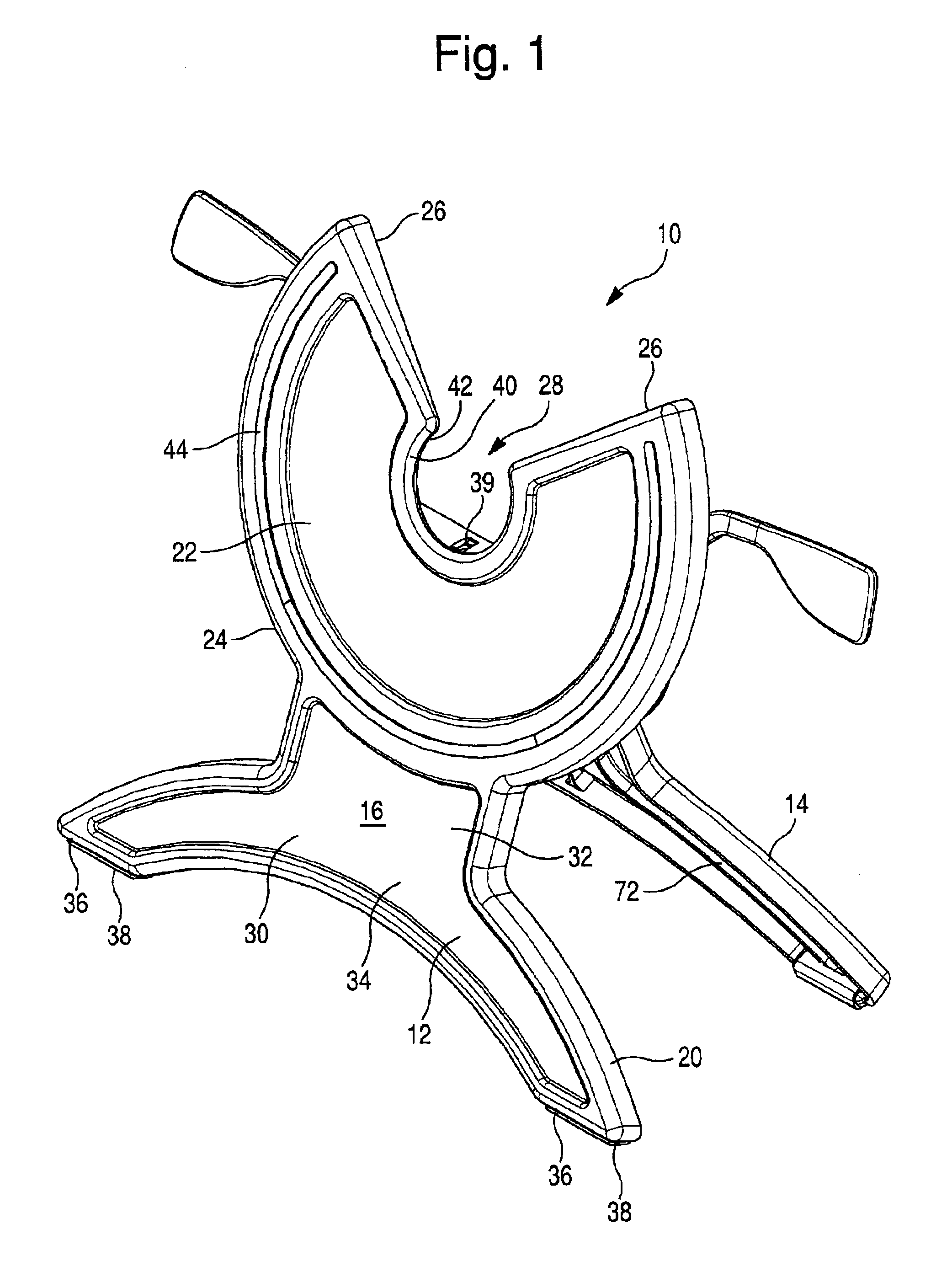
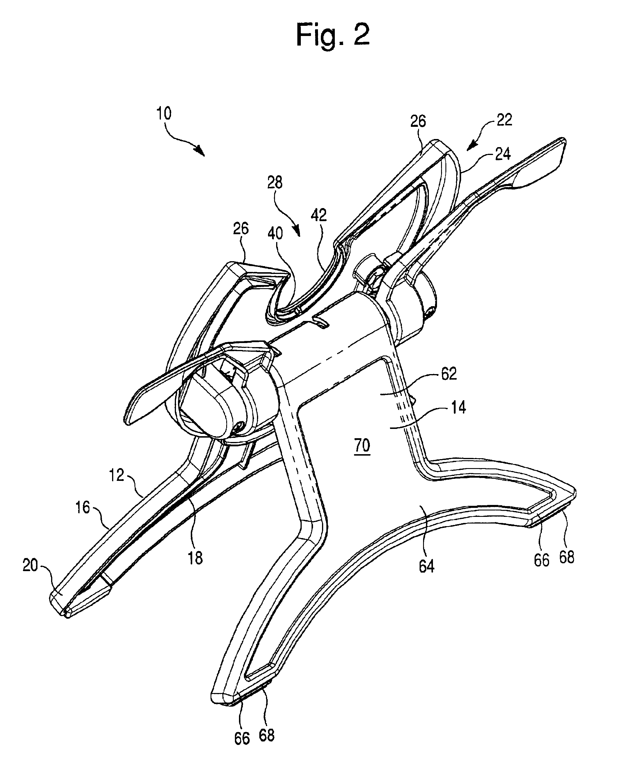
Stand for supporting a display in multiple orientations and a display used in combination with said stand
a technology for supporting a display and a stand, which is applied in the direction of machine supports, instruments, and electrical apparatus casings/cabinets/drawers, etc., which can solve the problems of not being able to rotate the screen and the housing, being difficult to support on one's lap, and not being able to remove the device. the effect of quick and easy removal
- Summary
- Abstract
- Description
- Claims
- Application Information
AI Technical Summary
Benefits of technology
Problems solved by technology
Method used
Image
Examples
second embodiment
the invention is shown in FIGS. 16-18. This embodiment uses the same lockable legs as the first embodiment but provide an alternate arrangement for rotatably attaching the display to the stand. Stand 200 of this embodiment comprises a planar front side that includes a notch 204 having bottom portion 206 comprising a segment of a circular arc. An arc-shaped wall 208 corresponding to the arc of portion 206 projects outwardly from portion 206 and terminates in a flange 210. While the front side is shown as having a shape generally like a section of a truncated cone, it could have other shapes, such as the C-shape of the front plate of the first embodiment, without departing from the scope of the invention, as long as an arc-shaped recess similar to that of the first or second embodiment is provided. Stand 200 is used with a display 212 that includes a rear wall 214 having an opening 216 which opens into a chamber 218 having a width greater than the width of opening 216. If the display ...
third embodiment
the invention is shown in FIGS. 19-21. In this embodiment, a stand 300 comprises a planar front wall 302, having a notch 304 with an arc-shaped end portion 306. A cradle 308 having a C-shaped bearing member 310 projecting from one side thereof is attached to front wall 302 with bearing member 310 engaged in end portion 306 of the notch. Cradle 308 includes a hooked lower portion 312 and two pegs 314 projecting from the edge of the cradle opposite hooked lower portion 312. A display 316 is used with this stand which display includes a housing 318 having a rear wall 320 which includes first and second holes 322. In use, a lower end of display 316 is placed into hooked lower portion 312 of cradle 308 and leaned back against the cradle until pegs 314 enter holes 322. This arrangement keeps the display firmly mounted in the cradle while the cradle is rotated with respect to the stand. A friction fit between the cradle bearing member 310 and arc-shaped end portion 306 allow the cradle to ...
fourth embodiment
the invention is shown in FIGS. 22-25 wherein a display 400 including a housing 402 having a rear surface 404 is provided with a rotatable bearing 406 on rear surface 404. Bearing 406 is centrally located on housing rear and includes a central opening 408 to accommodate a cable 410 emerging from the display so that bearing 406 can rotate around the cable without twisting or damaging the cable. Bearing 406 further includes two openings 412 which each of which preferably includes a pair of converging wall portions 414 meeting at a vertex 415. As best seen in FIG. 24, openings 412 each open into an interior chamber 416 that is wider than opening 412 thus forming a lip or flange 418 around each opening.
Display 400 is used with a stand 420 comprising a planar front side 422 having a V-shaped notch 424 and first and second projections 426 located one on either side of notch 424. Each projection includes a rod portion 428 and an end flange 430, and these projections are securely fastened t...
PUM
 Abstract
Description
Claims
Application Information
 - R&D
- Intellectual Property
- Life Sciences
- Materials
- Tech Scout
- Unparalleled Data Quality
- Higher Quality Content
- 60% Fewer Hallucinations
Browse by: Latest US Patents, China's latest patents, Technical Efficacy Thesaurus, Application Domain, Technology Topic, Popular Technical Reports.
© 2025 PatSnap. All rights reserved.Legal|Privacy policy|Modern Slavery Act Transparency Statement|Sitemap|About US| Contact US: help@patsnap.com


