Eureka AIR delivers breakthrough ideas for toughest innovation challenges, trusted by R&D personnel around the world.

Telescopically adjustable battery holddown

a technology of battery holddown and telescopic adjustment, which is applied in the direction of cell components, furniture parts, cell component details, etc., can solve the problems of automobile owners incurred additional costs, battery holddown cannot be used, and the manufacturer and supplier of added costs

Inactive Publication Date: 2005-03-29
QUICK CABLE
View PDF28 Cites 47 Cited by
  • Summary
  • Abstract
  • Description
  • Claims
  • Application Information

AI Technical Summary

Benefits of technology

A primary object of the present invention is to provide a novel battery holddown.
Another object of the present invention is to provide a novel battery holddown which fits batteries with different lengths or widths and heights.
Another object of the present invention to provide a battery holddown which is not susceptible to locking at fixed positions due to corrosion or the like.
Another object of the present invention is to provide a battery holddown which allows for length adjustment without requiring disassembly.
Another object of the present invention is to provide a battery holddown which allows for length adjustment solely by relative linear movement of the brackets.
Yet another object of the present invention is to provide a battery holddown which allows infinite length adjustment to provide for use with batteries of any length.

Problems solved by technology

Often a replacement or substitute battery is of a different case size than the original battery such that the holddown for the original battery cannot be used with the replacement or substitute battery.
Thus, added expense is encountered by the automobile owner because in addition to the battery, at least the holddown of the battery restraint system also has to be replaced.
Additionally, added expense to the manufacturer and supplier of battery holddowns occurs as battery holddowns for all sizes of batteries manufactured are generally required to be maintained in inventory.
Although known, most adjustable battery holddowns to fit different sizes of batteries in the past have not achieved the same commercial success as nonadjustable battery holddowns.
Particularly, the adjustment mechanisms of prior adjustable battery holddowns were typically of a complicated design and were susceptible to corrosion from battery acid and other elements in the environment.
Although adjustable when manufactured, corrosion often locked components together or otherwise prevented adjustment such that replacement was necessary if a different size battery was desired to be held.
Additionally, some adjustable battery holddowns were adjustable in only a single direction such as length such that they could not be utilized with batteries of different sizes in the direction which they were not adjustable.
However, the Johnson devices present other problems in use.
In addition, the Johnson devices provide for adjustment of length only to predetermined increments and do not provide for length adjustment while engaging the bolts and battery tray.
The Johnson brackets are also difficult to handle since, when not drawn tight against a battery they separate.
The use of numerous parts to allow length adjustment is costly and complicated.
In addition, Burkholder et al. does not provide for height adjustment.

Method used


Image

  • Telescopically adjustable battery holddown
  • Telescopically adjustable battery holddown
  • Telescopically adjustable battery holddown

Examples


Embodiment Construction

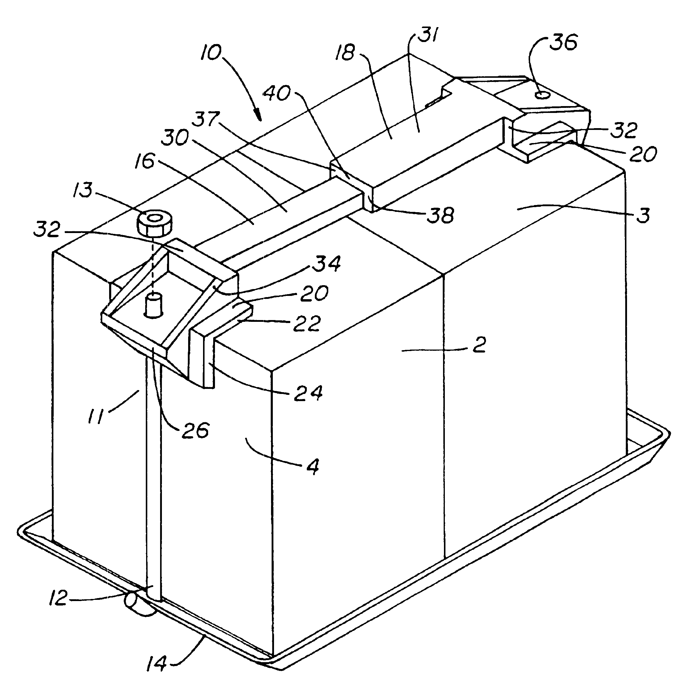
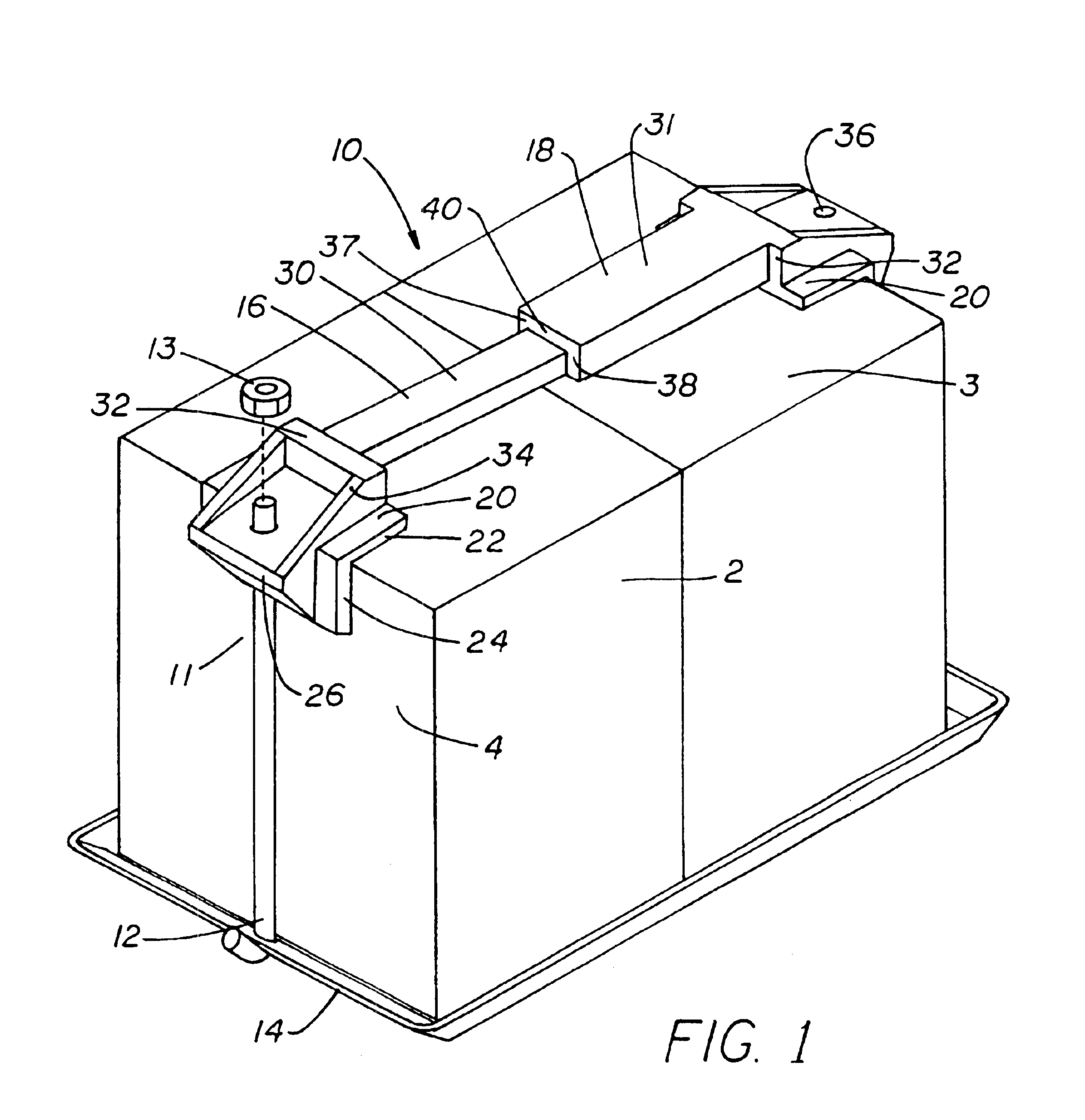
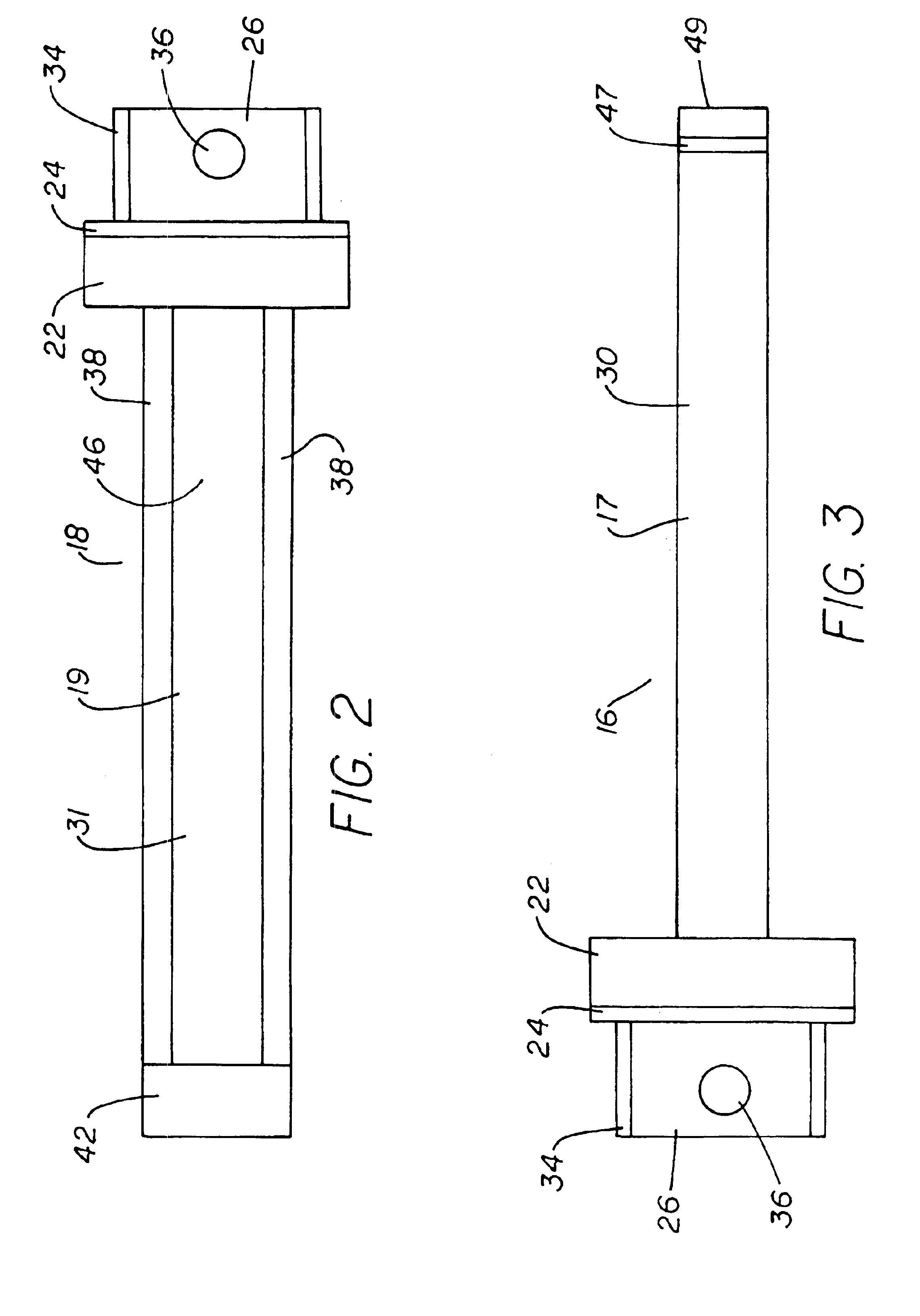
A battery holddown according to the preferred teachings of the present invention is shown in the figures and is generally designated 10. Holddown 10 in the most preferred form is used with a pair of upright bolts 12 which extend from a tray 14 which supports the desired battery assembly 2. Bolts 12 and tray 14 can be of any conventional design such as those utilized in vehicles, heavy equipment, and like applications. As shown in FIG. 1, bolts 12 have a hooked lower end which is fitted through an aperture in tray 14. Holddown 10 generally includes first and second battery brackets 16,18. Brackets 16,18 generally include L-shaped clamps 20. Clamps 20 each include a first portion such as a top member or plate 22 for abutting with the top 3 of battery assembly 2 and a second portion such as a side member or plate 24 for abutting with the side 4 of battery assembly 2 and extending generally perpendicular to top plate 22. Top and side plates 22 and 24 have a generally equal length, with ...


PUM

PropertyMeasurementUnit
lengthaaaaaaaaaa
sizesaaaaaaaaaa
widthaaaaaaaaaa

Abstract

A telescopically adjustable holddown (10) is disclosed including first and second brackets (16,18) and drawing elements (12) adapted to extend between a battery tray (14) and the brackets for drawing the brackets toward the battery tray to hold a battery (2). The brackets each include a generally L-shaped clamp (20) having top (22) and side members (24) for abutting the top (3) and sides (4) of the battery. An ear (26) extends from each side member and includes an aperture (36) for receiving a bolt (12) extending from the battery tray. Each bracket includes a cross rod (17,19) with second cross rod (19) having a cavity (46) for slidably receiving the first cross rod (17). The cavity requires that relative movement of the first and second brackets be substantially along the cavity axis (50) to allow telescopic assembly of the first and second brackets. The brackets are drawn toward the battery tray by tightening nuts (13) on the bolts to prevent relative movement of the brackets.

Description

FIELD OF THE INVENTIONThe present invention generally relates to devices for restraining objects of different sizes, particularly to devices for restraining batteries of different widths, and more particularly to battery holddowns for batteries supported in a battery tray.BACKGROUND OF THE INVENTIONA conventional manner for restraining batteries such as in the automotive industry is to support the battery in a tray and utilize a battery holddown which abuts the top of the battery and is drawn toward the tray utilizing bolts. It can also be appreciated that batteries come in a variety of case sizes depending upon the power requirements, the particular battery design, and the like and also depending upon the particular manufacturer. Often a replacement or substitute battery is of a different case size than the original battery such that the holddown for the original battery cannot be used with the replacement or substitute battery. Thus, added expense is encountered by the automobile ...

Claims


Application Information

Patent Timeline
Patent Type & Authority Patents(United States)
IPC IPC(8): A47B97/00B60R16/04H01M10/06H01M50/202H01M50/264
CPCA47G11/002H01M2/1072H01M2/1005H01M10/06Y02E60/10H01M50/256H01M50/264H01M50/202
Inventor SHANNON, JR., JOHN K.
Owner QUICK CABLE
Why Eureka
Eureka Blog
Learn More