
Structure for a toy gun

a toy gun and structure technology, applied in the field of toy gun structure improvement, can solve the problems of short fire range, poor precision and short precision range, waste of time, etc., and achieve the effect of improving structur

Inactive Publication Date: 2005-03-22
JZN AMY
View PDF13 Cites 28 Cited by
  • Summary
  • Abstract
  • Description
  • Claims
  • Application Information

AI Technical Summary

Benefits of technology

The main objective of the present invention is to offer an improved structure for a toy gun for solving aforesaid shortcomings. The present invention adopts rotating a knob to control movement of an adjusting rod, and also a leading rod in a rear portion; additionally, the knob may not leave its own original position although it is rotated. While rotating a pulling portion to let an injecting p

Problems solved by technology

Hence, a Flexible Fire-pin Gun with a flat head was generated but with many different types, it had being popular for a while and was with poor precision and a short range of fire.
Unfortunately, operations for the Air-soft Gun are very similar to rifle operations, that is, once to pull a trigger is only able to shoot one bullet; therefore a new toy gun with continuous shooting was developed and produced, and it was called Gas Gun by way of compressing CO2 to generate power.
As an example, some left gas in a gas tank suddenly blowing off causes accidents while the gas tank being dismantled.
That is, processes to dismantle for cleaning are complicate and spending time.

Method used


Image

  • Structure for a toy gun
  • Structure for a toy gun
  • Structure for a toy gun

Examples


Embodiment Construction

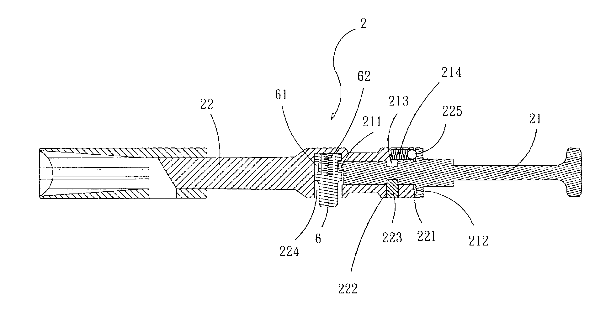
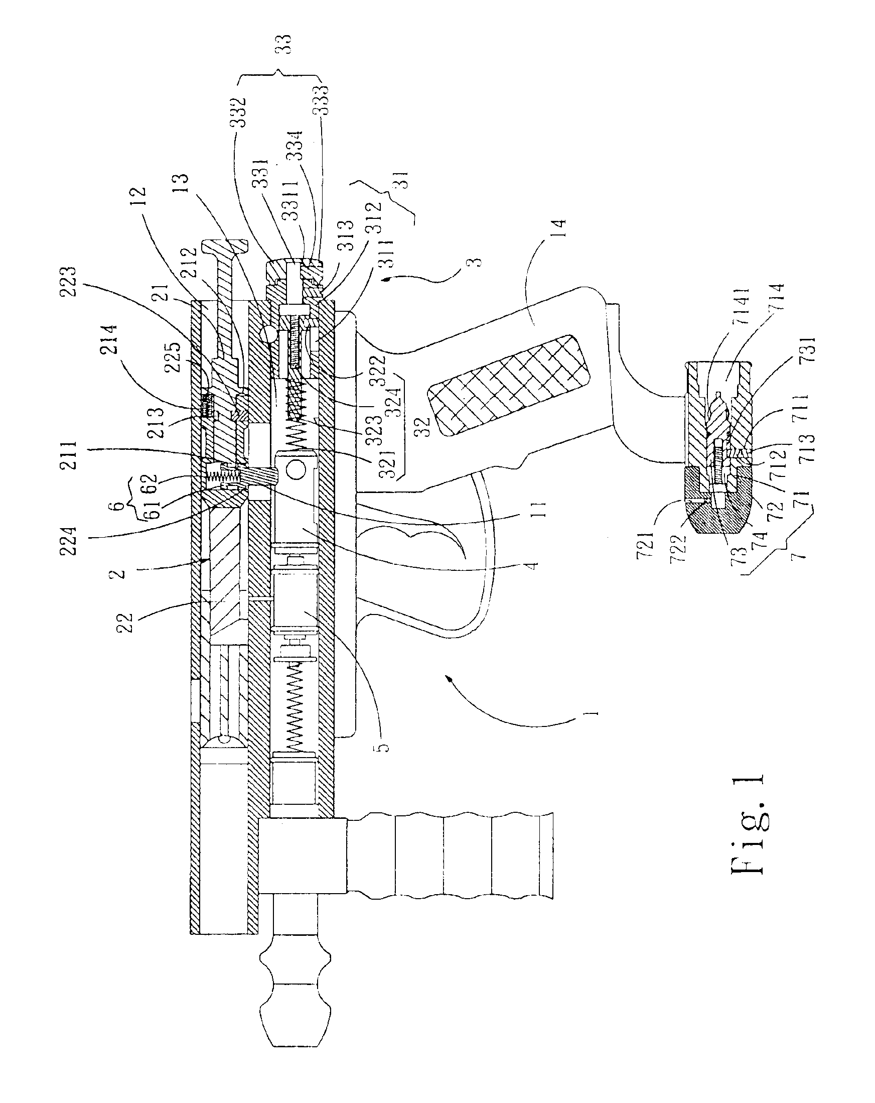
Please refer to FIG. 1, which is a sectional view of an assembly of the present invention. The present invention comprises a body 1, which includes an upper moving trough 12 and a lower moving trough 13, both are parallel to each other and connected via a connecting trough 11; inside the upper moving trough 12 is an extruder 2 and inside the lower moving trough 13 is arranged a rear portion 3, a mechanical component 4 connecting to the rear portion 3 and a valve controller 5 connecting to the mechanical component 4 in series from a rear end of the lower moving trough 13; wherein the mechanical component 4 connects to the extruder 2 via a connecting piece 6 penetrating through the connecting trough 11; the extruder 2 consists of a pulling portion 21 and an injecting portion 22, an end of the injecting portion 22 is out of the upper moving trough 12, and the connecting piece 6 is on the injecting portion 22; the rear portion 3 further includes a rear piece 31, inside the rear piece 31...


PUM


Abstract

The present invention discloses an improved structure for a toy gun comprises a body, which includes an upper moving trough and a lower moving trough, both are parallel to each other and connected via a connecting trough; inside the upper moving trough is an extruder and inside the lower moving trough is arranged a rear portion, a mechanical component connecting to the rear portion and a valve controller connecting to the mechanical component in series from a rear end of the lower moving trough. Wherein, for the design of the extruder, the connecting piece is driven by the pulling portion, thus to rotate the pulling portion is to generate relative and radial motions among the connecting piece in the connecting trough, the injection portion and the mechanical component; further that, the connecting piece is taken off from the mechanical component to terminate the connecting stage of the extruder and the mechanical component. To turn the knob of the rear portion is to simultaneously move the leading rod of the rear portion in the rear piece back and forth, and the knob may not have an axial movement from original position thereof. Further, to utilize the rotation of the rotating piece of the gas-control portion is capable of controlling the adjusting rod; hence the thimble of the gas-control portion being driven is to handle the combining body.

Description

BACKGROUND OF THE INVENTION1. Field of the InventionThe present invention generally relates to an improved structure for a toy gun, especially to the structure being dismantled very easily and enhanced safety.2. Description of the Prior ArtDuring 1970s, there were several types of toy guns, and most of them adopted springs to push toy bullets out. After several decades of years, human being life is built up to another stage so as to asking product qualities; besides, toy makers have being started to develop new toy guns with good appearances and more truth. Hence, a Flexible Fire-pin Gun with a flat head was generated but with many different types, it had being popular for a while and was with poor precision and a short range of fire. In the middle of 1990s, another Air-soft Gun via air-compression theory was derived. Unfortunately, operations for the Air-soft Gun are very similar to rifle operations, that is, once to pull a trigger is only able to shoot one bullet; therefore a new ...

Claims


Application Information

Patent Timeline
IPC IPC(8): F41B11/00
CPCF41B11/00
Inventor JZN, AMY
Owner JZN AMY
Learn More